46
1
Operation Manual Supply Unit SO CM-P BG1+2
ID no.: 1400.201B.5-00 Date: 02/2020
CAUTION!
DAMAGE TO THE DEVICE DUE TO CONNECTION OF AN EXT.
BRAKING RESISTOR!
x Carelessness may result in signicant damage.
Please note that no additional external braking resistor is allowed to be connected to the device
model "with integrated braking resistor".
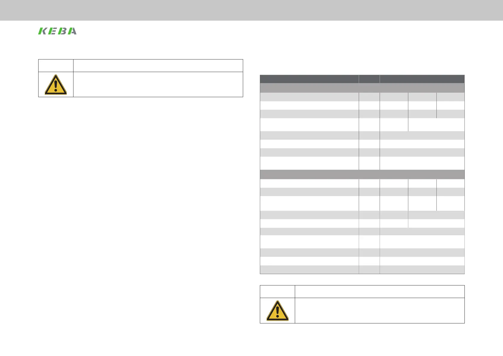
A.2 Technical data, supply unit BG2
Device Unit SOCM-P.0022 / SOCM-P.0122
Input, mains side
Mains voltage U
N
± 10%, 3 times V AC 230 400 480
Continuous current [A
AC eff
], typical A 46 46 38
Peak current [A
AC
], typical A 92 92 76
Continuous power, typical (depending on mains
impedance)
kVA 18.5 32
Rectier power dissipation W 110
Asymmetry of the mains voltage ±3 % max.
Frequency 50-60 Hz ± 10%
Max. cable cross-section of the terminals X12
1.5 ... 16mm
2
(ne-stranded cable with/without
ferrules)
DC link output
DC link voltage typical * V DC 325 565 678
Continuous current A DC 39 39 32
Peak current 2 x I
N
for 1 s
mains choke not required
A DC 78 78 64
Continuous power P
N
kW 12.5 22
Peak power 2 x P
N
for 1 s kW 25 44
DC link capacitance only CM-P µF 840
Required total DC link capacitance for continuous
power
µF 2200
Permissible DC link capacitance SOCM + CM-P µF 4000 (3160 + 840) max.
Power dissipation P
rated
in the interior W 130
* Load-dependent
Table A.3 Technical data, ServoOne CM-P BG2
CAUTION! DAMAGE TO THE SUPPLY UNIT DUE TO OVERLOAD IN THE DC LINK!
x Carelessness may result in signicant damage.
The maximum overall capacitance of the multi-axis system DC link must not exceed the value
stated.
 Loading...