47
1
Operation Manual Supply Unit SO CM-P BG1+2
ID no.: 1400.201B.5-00 Date: 02/2020
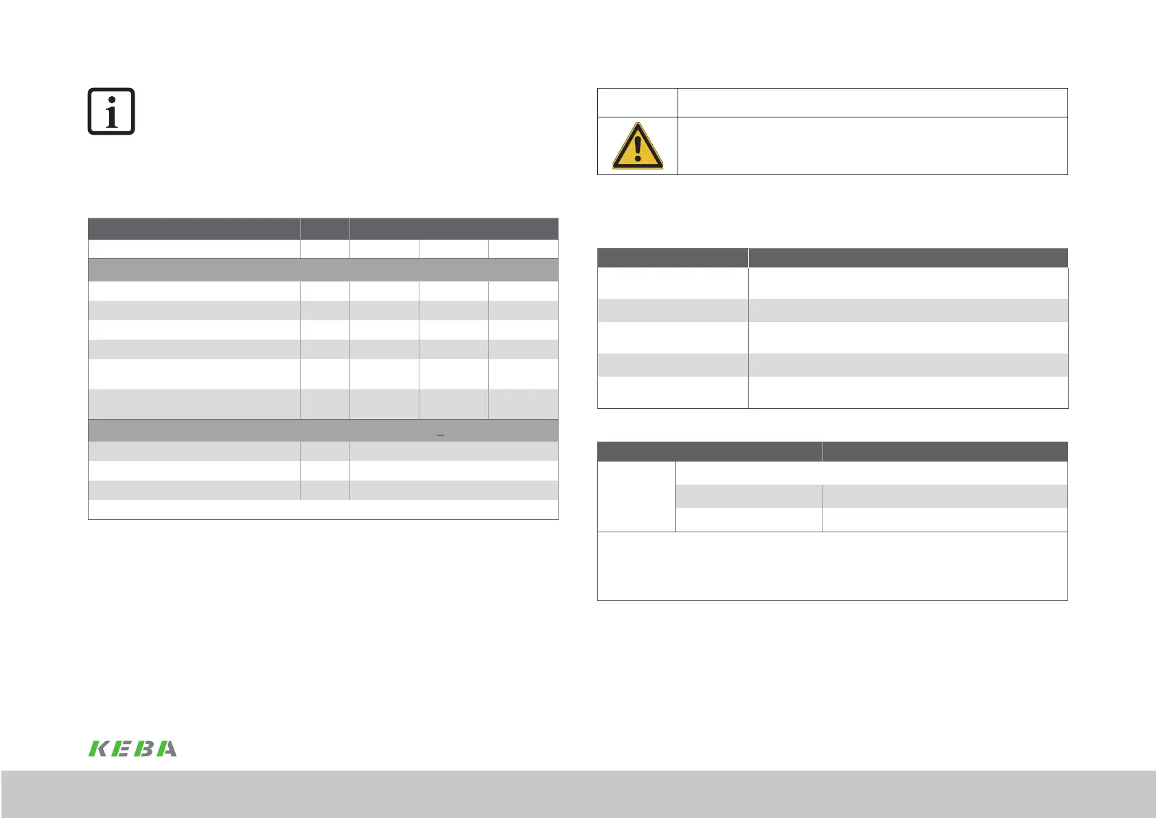
CAUTION!
DAMAGE TO THE DEVICE DUE TO CONNECTION OF AN EXT.
BRAKING RESISTOR!
x Carelessness may result in signicant damage.
Please note that no additional external braking resistor is allowed to be connected to the device
model "with integrated braking resistor".
A.3 Ambient conditions
Ambient conditions ServoOne CM-P supply unit
Protection
Device: IP20 - exception terminals: IP10 (protection against touching, back of
hand)
Accident prevention regulations As per the local regulations (in Germany e.g.BGV V3)
Installation altitude
Up to 1000 m aboveMSL, higher with power reduction
(1% per 100m, max. 2000m abovesea level)
Pollution degree 2
Type of mounting
Built-in unit, only for vertical mounting in a switch cabinet with min. IP4x
protection, on using STO safety function min. IP54
Table E.5 Ambient conditions, ServoOne CM
Climatic conditions ServoOne CM-P supply unit
In transit
As per EN61800-2, IEC60721-3-2 class 2K3
1)
Temperature -25°C to +70°C
Relative atmospheric humidity 95% at max. +55°C
1) The absolute humidity is limited to max. 60g/m³. This means, at 70°C for example, that the relative atmospheric humidity
may only be max. 40%.
2) The absolute humidity is limited to max. 29g/m³. So the maximum values for temperature and relative atmospheric humidity
stipulated in the table must not occur simultaneously.
3) The absolute humidity is limited to max. 25g/m³. That means that the maximum values for temperature and relative atmos-
pheric humidity stipulated in the table must not occur simultaneously.
Table A.6 Climatic conditions, supply unit ServoOne CM-P
NOTE:
In the overall axis group, a DC link capacitance of ≥ 100µF/kW (for 3 x 400V)
or ≥ 170µF/kW (for 3 x 230V), referred to the highest rated power that
occurs, must be provided. This capacitance is determined by adding together
the capacitances of the individual devices. The root mean square of the active
power for a load cycle is dened as the active power.
A.2.1 Technical data, brake chopper BG2
Device Unit SOCM-P.0022 / SOCM-P.0122
Mains voltage V AC 230 400 480
Brake chopper power electronics
Brake chopper switching threshold V 411 652 765
Overvoltage protection V 446 687 800
Continuous braking power [kW] kW 3.5 6 6
Peak braking power for maximum 0.5 s *) kW 20 28 30
Maximum ohmic resistance of an externally
connected braking resistor
Ω 50 90 90
Minimum ohmic resistance of an externally installed
braking resistor
Ω 8 15 20
Supply unit "with integrated braking resistor" (version SO CM-P.xxxx.11xx.x)
Continuous braking power [kW] W 200
Peak braking power for maximum 0.5 s *) kW 6
Ohmic resistance of the integrated braking resistor Ω 28
*) After this time shutdown is initiated based on I
2
x t
Table A.4 Brake chopper BG2
 Loading...