26
1 Electrical installation
Operation Manual Supply Unit SO CM-P BG1+2
ID no.: 1400.201B.5-00 Date: 02/2020
Electrical installation
4.5 Electrical isolation concept
The control terminals are designed as protective extra low voltage (PELV) circuits and
must only be operated with such PELV voltages, as per the relevant specication. This
design provides reliable protection against electric shock on the control side.
The connections X1, X5, X7, X8 are at mains potential (low voltage).
The overview opposite shows the potential references for the individual connections in
detail. This concept also delivers higher operational safety and reliability of the supply
unit.
Supply unit
connections (11)
Description Potential
Abbre-
viation
X1 /BR
Connection for external braking resistor
(connected to DC link)
Low voltage
1)
ZK
X1/ϑ
Connection for temperature monitoring,
braking resistor (Klixon)
Extra low voltage with
basic insulation
2)
BI
X2/ 24 V DC 24 V switched-mode power supply output
Protective extra low voltage
circuit
3)
PELV
X3 Cross-communication
Protective extra low voltage
circuit
3)
PELV
X5 Relay contact, programmable Reinforced insulation
4)
VI
X6 /TP Two test pulse outputs
Protective extra low voltage
circuit
3)
PELV
X6/ RO01 Relay changeover contact, programmable
Protective extra low voltage
circuit
3)
PELV
X7 Mains supply, switched-mode power supply Low voltage
1)
Mains
X8 Mains supply, DC link Low voltage
1)
Mains
Busbars 24 V 24 V switched-mode power supply output
Protective extra low voltage
circuit
3)
PELV
Busbars DC Link DC link Low voltage
1)
ZK
1) Low voltage ≤ 1000 V AC or ≤ 1500 V DC
2) Single isolation from the low-voltage network: PELV networks are not allowed to be connected.
3) PELV = Protective Extra Low Voltage AC: U ≤ 50 V
A connection for the extra low voltage can be earthed.
4) Safe isolation from the low-voltage network and PELV network. A PELV or also a low voltage (max. 250 V AC) is
allowed to be connected.
Table 4.3 Key to the overview "Electrical isolation concept"
You will nd a wiring example for the axis group in which you will also nd detailed
information on the protective earth conductor connections in Figure 4.17
PE
4 1 2 3
5
6
6
7
8
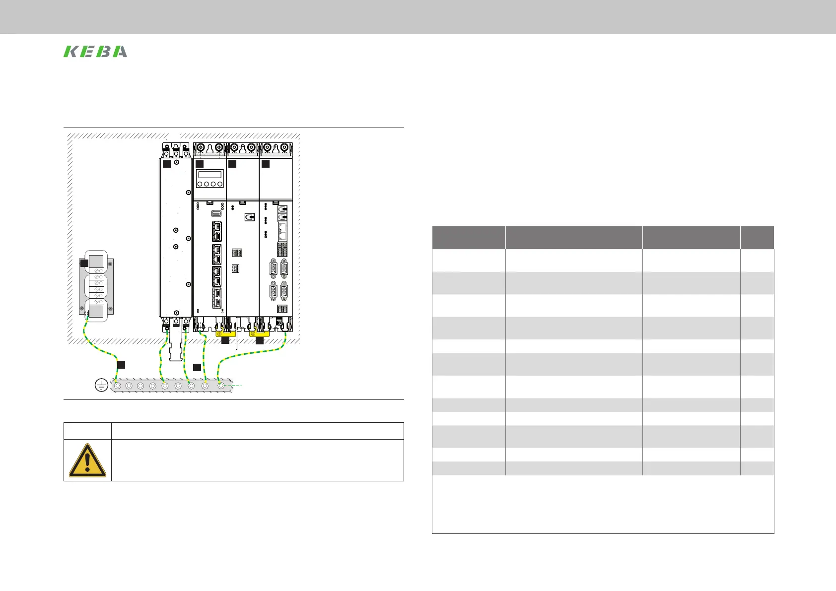
1. MotionOne CM controller
2. ServoOne CM-P supply
unit
3. ServoOne CM axis
controller
4. Mains lter
5. Mains choke
6. Series earthing with PE
connectors
7. Star topology earthing
8. Double earth connection
9. We recommend the
additional Cu strap
(1410..579.0) between
the mains lter and the
rst component in the
row to improve the EMC
properties. See Figure 4.2.
Figure 4.5 Protective earth conductor connection with double PE conductors
CAUTION! Risk of injury due to incorrect wiring!
Carelessness may result in injuries.
x The protective earth conductor connection is a safety feature. Therefore, make sure that all
connections have good contact and are sufciently secure that they cannot come loose.
 Loading...