20
Mechanical installation
Operation Manual Supply Unit SO CM-P BG1+2
ID no.: 1400.201B.5-00 Date: 02/2020
Mechanical installation
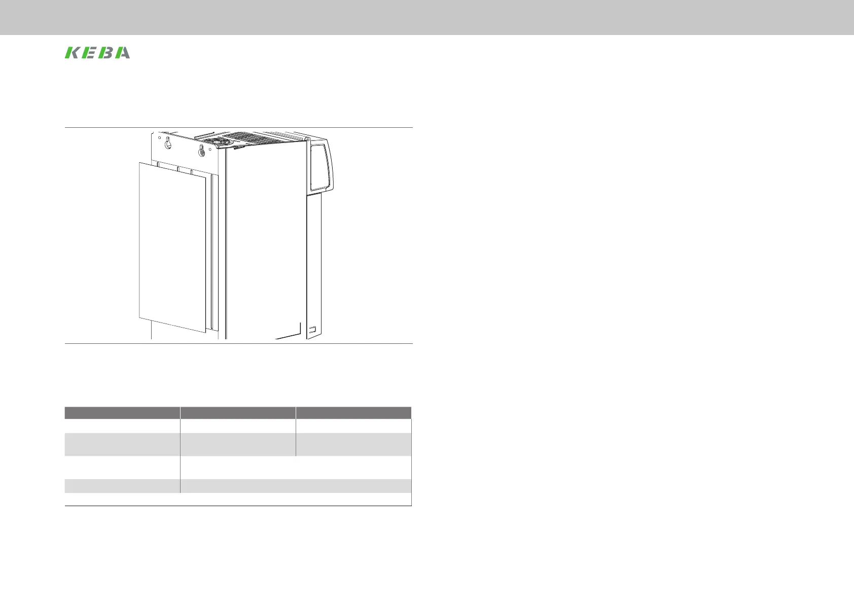
As the devices of size BG2 are twice as wide, a correspondingly wider piece of thermally
conductive lm is attached to the cooling plate (see Fig. Figure 3.9).
Figure 3.9 Rear wall with lm ServoOne CM axis controller BG2 (cold plate)
3.5.3 Sizing the cooler
ServoOne CM-P BG1 ServoOne CM-P BG2
Thermal resistance R
th
K
1)
0.02 K/W 0.01 K/W
Thermal capacity
of the cooling plate at the device
390 Ws/K 780 Ws/K
Max. temperature
of the cooling plate at the device
85 °C
Surface nish on the cooler Max. roughness R
Z
= 6.3
1) Thermal resistance between active cooling surface on the device and cooler
Table 3.3 Characteristics of cold plate model
 Loading...