42
1 Design variants
Operation Manual Supply Unit SO CM-P BG1+2
ID no.: 1400.201B.5-00 Date: 02/2020
Design variants
X6
X11
X8
X5
L1 L3L2
1116 12
X6
X7
L1 L2
24 V
GND
BR
BR
ϑ
ϑ
X2
n.c.
n.c.
X5.1
X3 X3
X4
X5.2
DC Link -
DC Link+
GND
+24 V
X1
X6
TP
4
9
10
20
L1 L2 L3 PEL1 N
L3
L2
L1
L3.1
L2.1
L1.1
1
3
2
7
6
8
24
14
13
5
L3
L2
L1
L3.1
L2.1
L1.1
3.1 3.2
W
U
V
X12
Motor
3~
ϑ
3
2
2
W
U
V
X1
Motor
3~
ϑ
3
2
17 18
19
21
25
15
ϑ
PE
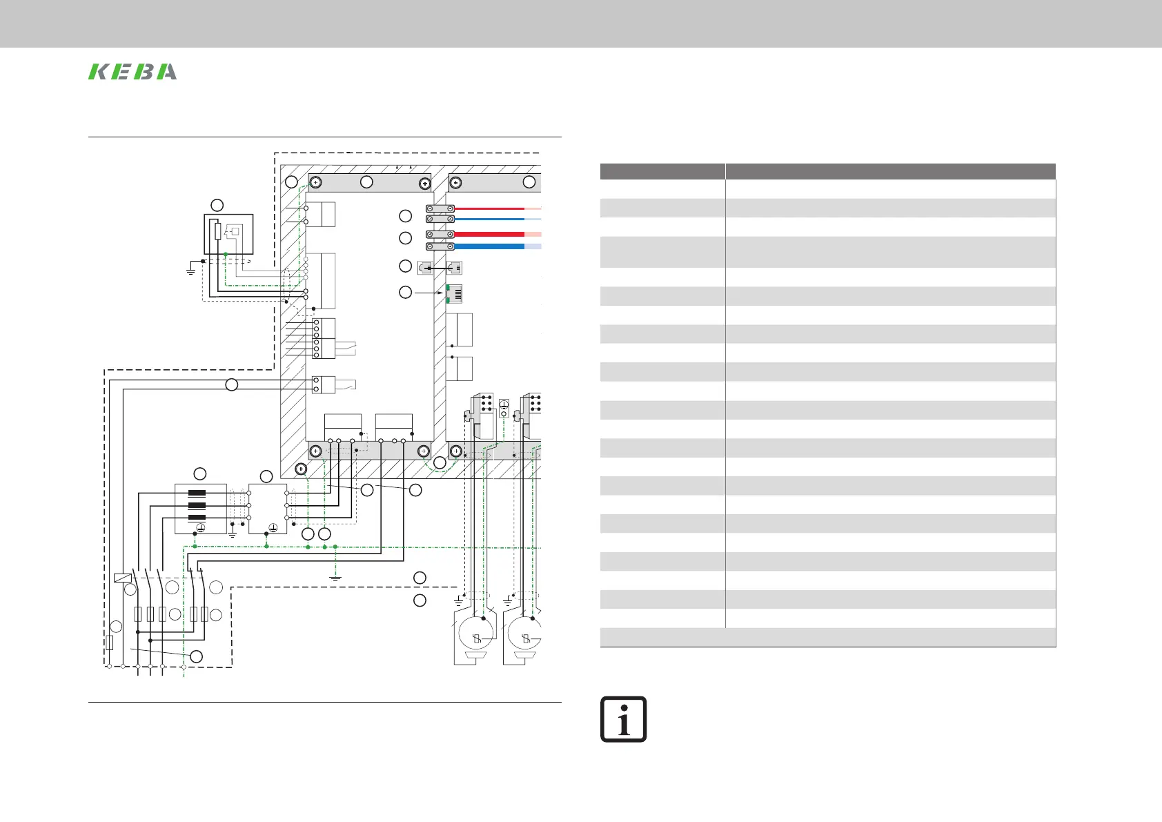
Figure 6.1 Connection example (schematic depiction). For key, see next page.
Key to connection example
Designation
(1) Mains fuses for DC link supply
(2) Mains fuse for switched-mode power supply
(3.1) Mains contactor normally open contact
(3.2)
Mains contactor normally closed contact for the disconnection of the SMPS
supply
(4) Programmable switching contact for mains contactor
(5) Mains choke (accessory)
(6) Mains lter (accessory)
(7) AC mains connection (power supply)
(8)* AC mains connection (24 V switched-mode power supply)
(9) Busbars DC link
(10) Busbars 24 V DC (PELV)
(11) Supply unit (SO CM-P)
(12) (21) (22) (23) See Operation Manual Axis Controller (SO CM)
(13) Switch cabinet
(14) Field
(15) External braking resistor with temperature monitoring
(16) Backing plate
(17) Backing plate earthing
(18) PE - protective earth conductor connection
(19) Series protective earth conductor connection to the next device
(20) Cross-communication
(24) Supply point, switch cabinet
(25) Cable protection 6 A gG
* The SMPS must be connected on the mains side at the supply point (24).
Table 6.1 Key to connection example
NOTE:
The supply unit does not protect the upstream components (3, 5, 6) against
thermal or electrical hazards. Corresponding protective measures are to be
taken.
 Loading...