6-4 External Triggering (Model 2306-VS Only)
Trigger signals
General waveforms for the trigger signals are shown in Figure 6-3 and Figure 6-4. Note that
both input and output triggers may be programmed fo
r either rising-edge or falling-edge
operation (see “Commands” topic later in this section).
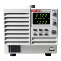
Figure 6-3
Trigger input signal
Triggers Step On
Leading Edge
High
(3V-5V)
Low
(
<0.8V)
2 μs
Minimum
A. Falling Edge Input Trigger
Triggers Step On
Leading Edge
High
(3V-5V)
Low
(
<0.8V)
2 μs
Minimum
B. Rising Edge Input Trigger
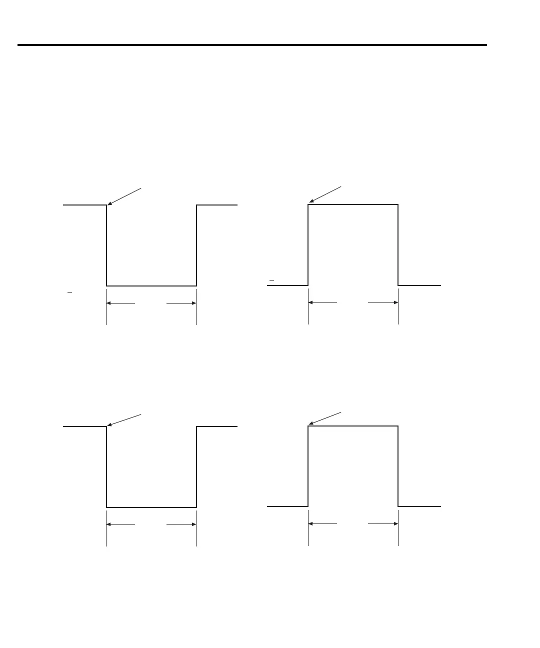
Figure 6-4
Trigger output signal
Trigger Occurs at
End of Step
10 μs
A. Falling Edge Output Trigger
Triggers Occurs at
End of Step
10 μs
B. Rising Edge Output Trigger
>4V
≤0.8V
>4V
≤0.8V
Test Equipment Depot - 800.517.8431 - 99 Washington Street Melrose, MA 02176
TestEquipmentDepot.com