E-2 Applications Guide
Simulating battery impedance
Variable output impedance control on channel #1
The electronic resistance of batteries varies according to a variety of factors such as but not
limited to chemistry, cell construction, number of charge/discharge cycles, temperature, and
depth of discharge. If a battery is used as a source in a circuit with a dynamic load, changes in
the voltage across the load will be produced proportional to the electronic resistance of the
battery and other sources of resistance in the circuit. If the peak load current is high enough or
the electronic resistance of the battery and the resistance between the source and the DUT is
large, the voltage drop will compromise the performance of the device.
This phenomenon occurs in TDMA and GSM cellular handsets where the magnitude of the
“ON/O
FF” current during transmission varies by as much as a factor of 20. In the absence of any
filtering capacitance between the battery and the RF power amplifier, the handset will shutoff if
the supply voltage is below the operating threshold for periods as short as several microseconds.
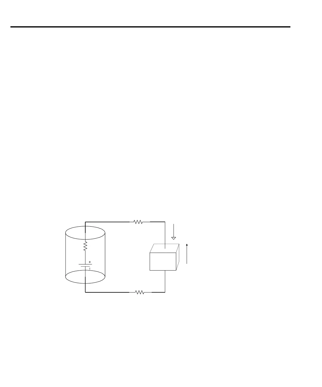
Figure E-1 sho
ws a simple schematic of a battery, represented by an ideal voltage source,
V
cell
, the internal impedance, R
i
(t), connected to a DUT with interconnects having a resistance
R
interconnect
.
Figure E-1
R
interconnect
R
interconnect
V
cell
R
i
(t)
V(t)
I(t)
Cell or Battery Pack
DUT
Battery schema.tic
If R
interconnect
is small compared to R
i
(t) and R
i
(t) is relatively constant during the length of
the pulse, R
i
(t) ~ R
i
,
then the voltage across the DUT may be expressed as:
Vt() V
i
It()R
i
–=
where: I(t) is the time varying current through the battery.
Test Equipment Depot - 800.517.8431 - 99 Washington Street Melrose, MA 02176
TestEquipmentDepot.com