Applications Guide E-3
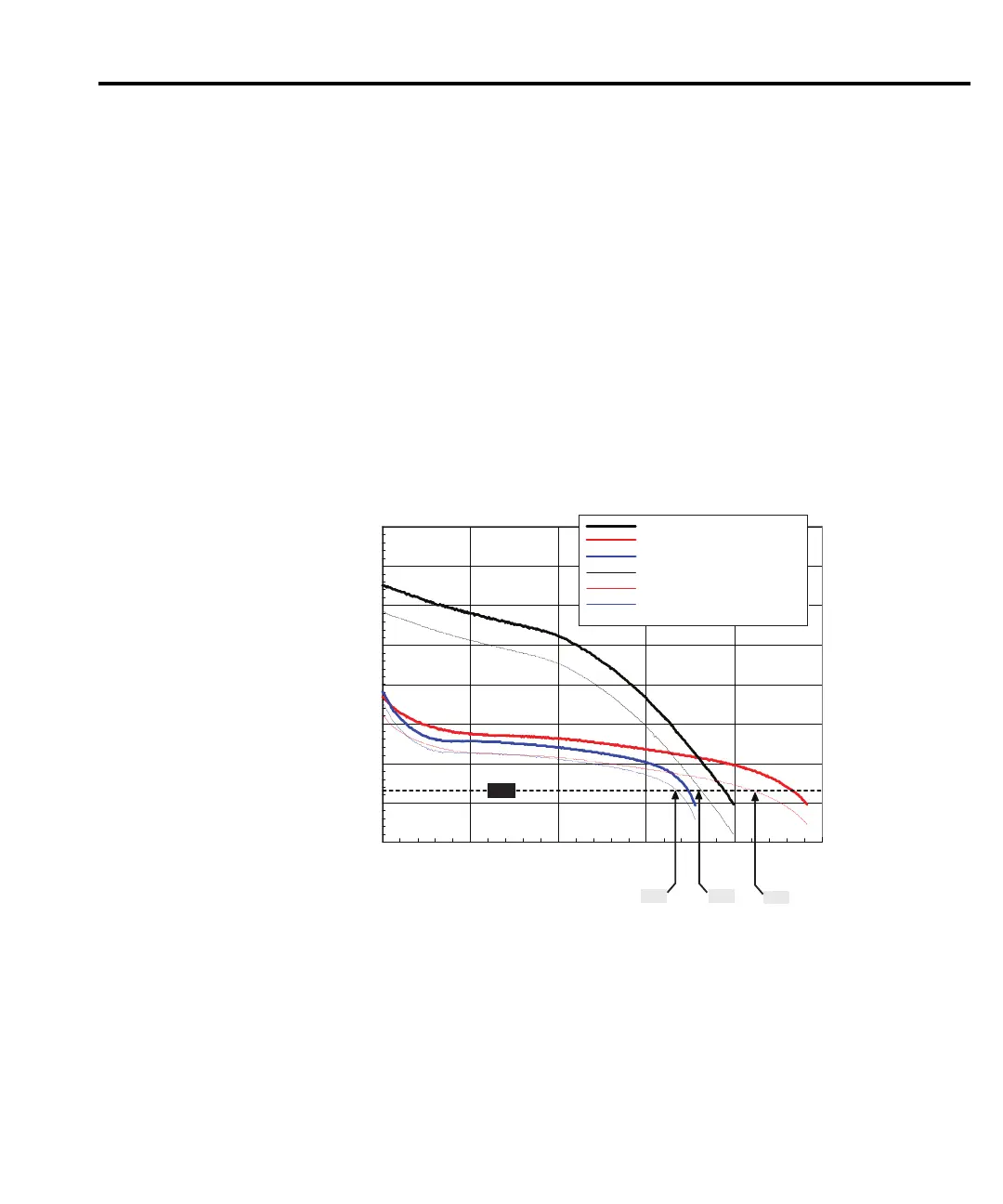
Figure E-2 shows the actual performance of typical LI, NiMH, and NiCd handset battery
packs with a dynamic load, shown in Figure E-3, simulating a GSM handset during
transmission. The pulse minimum voltage is the v
oltage at the battery terminals during the
transmit, or high current portion, of the data frame. The average battery voltage is the voltage
across the terminals measured with a 6½ digit DMM at approximately 50 readings per second.
The figure shows the pulse minimum voltage reaches the shutdown threshold, 5.7V, before
average battery voltage. The difference between the pulse minimum and average battery voltage
also varies as a function of the electronic resistance with time, shown in Figure E-4 of the battery
packs and ranges between 200–500mV. The results of these measurements prove that the
impeda
nce of the battery must be considered when evaluating handset performance, especially
near the end of life for the battery pack.
NOTE Figure E-2 shows the average and minimum battery pack terminal voltage during a
load pulse from a dynamic load simulating a GSM phone.
Figure E-2
5.00
5.50
6.00
6.50
7.00
7.50
8.00
8.50
9.00
0.0 2.0 4.0 6.0 8.0 10.0
Battery Voltage
Volts
Time
hrs
5.7V
6.59
8.15
7.18
Li ion AverageBattery Voltage
NiMH Average Battery Voltage
NiCd Average Battery Voltage
Li ion Battery Pulse Minimum Voltage
NiMH Battery Pulse Minimum Voltage
NiCd Battery Pulse Minimum Voltage
Actual battery pack terminal voltage during GSM phone simulation
Test Equipment Depot - 800.517.8431 - 99 Washington Street Melrose, MA 02176
TestEquipmentDepot.com