E-4 Applications Guide
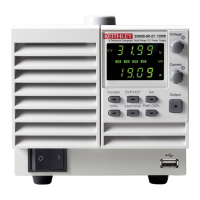
Figure E-3
Current
Voltage
Pulse Minimum Voltage
-0.030 amps
-1.200 amps
Simulated GSM phone current profile
NOTE The simulated GSM phone current profile contained in Figure E-3 shows a standby
current of 0.030A, a transmit current of 1.2A, and the pulse minimum voltage during
the tr
ansmit frame.
Channel #1 of the Model 2306 has a variable output impedance control that can be used to
simu
late the impedance of a battery pack. The output impedance may be set from 0.00Ω (default
condition) to 1.00Ω in 0.01Ω increments from the front panel or over the GPIB bus.
Time, hrs
Output Impedance, ohms
0.0
2.0 4.0 6.0 8.0 10.0
NiMH
NiCd
Li ion
0.10
0.15
0.20
0.25
0.30
0.35
0.40
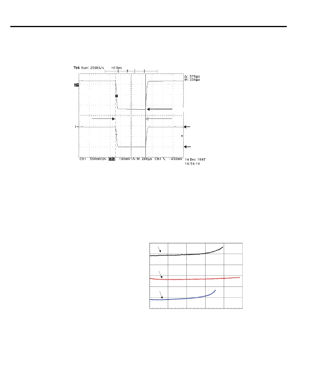
Figure E-4
Electronic resistance of NiCd, NiMH, and
Li ion battery packs
NOTE Figure E-4 shows electronic resistance for battery packs during a simulated GSM
phone pulsed discharge from full charge to 5.5 volts.
Test Equipment Depot - 800.517.8431 - 99 Washington Street Melrose, MA 02176
TestEquipmentDepot.com