SECTION 6
Theory of Operation
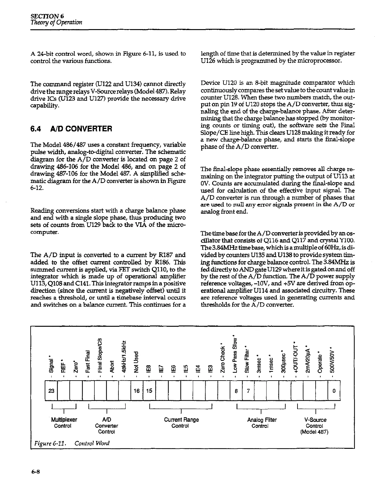
A 24bit control word, shown in Figure 6-11, is used to
control the various functions.
The command register (UK22 and U134) cannot directly
drive the range relays V-Source relays fMode1487). Relay
drive KS (Ul23 and U127) provide the necessary drive
capability.
6.4 A/D CONVERTER
The Model 4W437 uses a constant frequency, variable
pulse width, analog-to-digital converter. The schematic
diagram for the A/D converter is located on page 2 of
drawing 486-106 for the Model 436, and on page 2 of
drawing 487-106 for the Model 437. A simplified sche-
matic diagram for the A/D converter is shown in Figure
6-12.
Reading conversions start with a charge balance phase
and end with a single slope phase, thus producing two
sets of counts from U129 back to the VIA of the micro-
computer.
The A/D input is converted to a current by R187 and
added to the of&et current controlled by RX%. This
summed current is applied, via FRT switch QllO, to the
integrator which is made up of operational amplifier
U113,Q108andC141.Thisintegratorrampsinapositive
direction (since the current is negatively offset) until it
reaches a threshold, or until a tiebase interval occurs
and switches on a balance current. This continues for a
length of time that is determined by the value in register
U126 which is programmed by the microprocessor.
Device U120 is an S-bit magnitude comparator which
continuously compares the set value to the count value in
counter U128. When these two numbers match, the out-
put on pm 19 of U120 stops the A/D converter, thus sig-
naling the end of the charge-balance phase. After deter-
mining that the charge balance has stopped (by monitor-
ing counts or timing out), the software sets the Final
Slope/GE line high. This clears U128 making it ready for
a new charge-balance phase, and starts the final-slope
phase of the A/D converter.
The final-slope phase essentially removes all charge re-
making on the integrator putting the output of U113 at
OV. Counts are accumulated during the final-slope and
wed for calculation of the effective input signal. The
A/D converter is run through a number of phases that
are used to
null
any error signals present in the A/D or
analog front end.
ThetimebasefortheA/Dconvarterisprovidedbyanos-
cillator that consists of Q116 and Q117 and crystalYlO0.
The3.S4h4Hstimebase,whichisamultipleof6OHz,isdi-
vided by counters U135 and U13S to provide system thn-
ing functions for charge balance control. The 3.34M?iz is
feddirectly toANDgateU129 whereitisgated onandoff
by the rast of the A/D functton. The A/D power supply
reference voltages, -lOV, and +5V are derived from op-
erational amplifier U114 and associated circuitry. These
are reference voltages used in generating currents and
thresholds for the A/D converter.
current Range
Analog Filter
Control
Control
V-Source
control
(Model 487)
Figure 6-11. Control Word
6-S