SECTION 7
hdaintemue
-
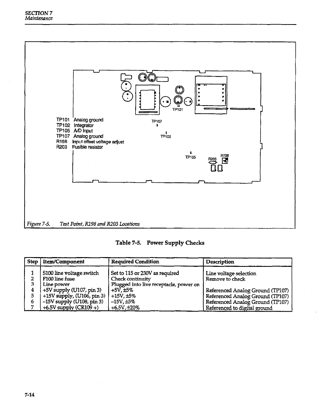
TP101 Analog ground
TP102 Integrator
TP105 ND Input
TP107 Analog ground
R198
Input offset voltage adjust
WO3
Fusib!e resistor
‘ipre 7-5. Test Point, Rl98 and R203 Locations
Table 7-5.
Power Supply Checks
I Steu I ItemlComuonent
1 Reauired Condition
1 Descriotion
I I
1
SIOO line voltage switch
Set to 115
or 230V as
required
2
FlOO line fuse
Check continuity
Line voltage selection
Remove to check
i
Line power
I Plueeed into live receutacle. Dower on I
+5V supply lJJ107, pin 3)
+.5QS%
I
. .
5
+15V supply, (U106, pin 3)
+lSV, &5%
Referenced Analog Ground (‘lT107)
6
-15v supply uJ108, pin 3)
-15v, &5%
Referenced Analog Ground (TF’107)
7
+6.sv supply
Pzlwl9
+)
+6.5v, -00%
Referenced Analog Ground (TPlO7)
Referenced to digital ground
7-14