Capacitance Limits
The following table describes the maximum load capacitance that can be tolerated in a series
configuration. If you suspect that your load capacitance exceeds these values, you must install the
series diode as previously described.
1 kW Models
in series
Maximum load capacitance with 2 units
in series
2 kW Models
in series
Maximum load capacitance with 2 units
in series
N6950A/N7950A 381 µF
N6970A/N7970A 763 µF
N6951A/N7951A 94 µF N6971A/N7971A 188 µF
N6952A/N7952A 23 µF N6972A/N7972A 46 µF
N6953A/N7953A 11 µF N6973A/N7973A 22 µF
N6954A/N7954A 6 µF N6974A/N7974A 12µF
N6976A/N7976A 5.5µF
N6977A/N7977A 3µF
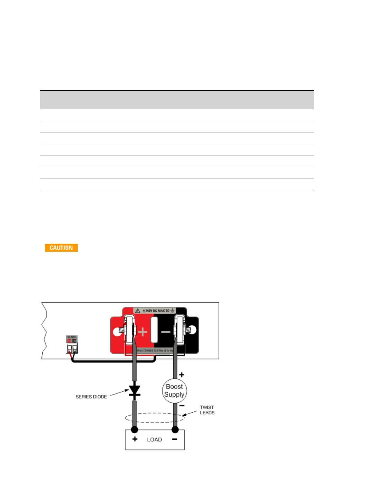
Additional Cautions When Using a Boost Supply in Series
The following cautions only apply to 40V, 60V, 80V, 120V and 160V N6900 models without relay
disconnect option 760 or 761.
To Prevent Possible Equipment Damage:
l Do not power up the boost supply until after the APS is turned on and initialized.
l Turn off the boost supply first; then turn off the APS unit.
The following figure illustrates how a boost supply is typically connected.
2 Installing the Instrument
82 Keysight N6900/N7900 Series Operating and Service Guide