Service 7
Keysight 85024A User’s and Service Guide 61
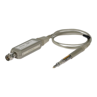
2 Follow the procedure in “Replacing the amplifier microcircuit” on page 66, to
remove the probe’s nose assembly, amplifier microcircuit, elastic conductive
strip, and spring clip. These items are illustrated in Figure 7-3, “High frequency
probe” on page 62.
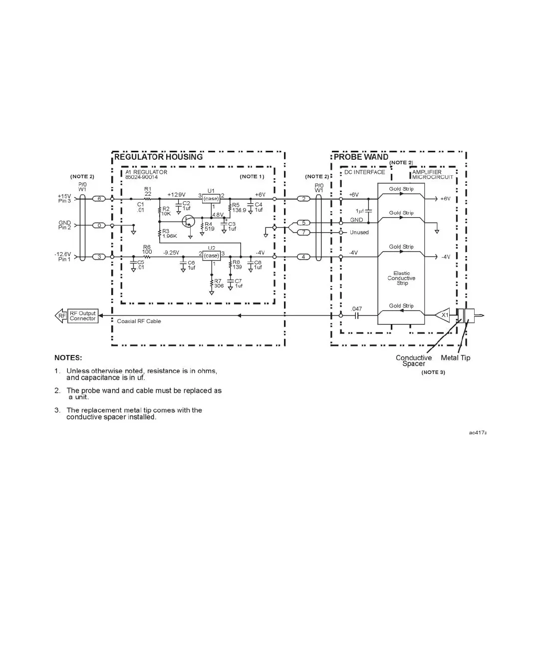
Figure 7-2 A1 regulator schematic diagram and overall block diagram