Keysight 85024A User’s and Service Guide 11
List of Figures
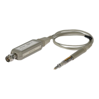
Figure 1-1 Probe with 10:1 divider and anti-static protection
cap . . . . . . . . . . . . . . . . . . . . . . . . . . . . . . . . . . . . . .16
Figure 2-1 Probe features . . . . . . . . . . . . . . . . . . . . . . . . . . . . . . .22
Figure 2-2 Exploded view of 10:1 divider . . . . . . . . . . . . . . . . . . .26
Figure 6-1 Replaceable parts identification . . . . . . . . . . . . . . . . .53
Figure 7-1 Probe tip input circuit . . . . . . . . . . . . . . . . . . . . . . . . . .59
Figure 7-2 A1 regulator schematic diagram and overall block
diagram . . . . . . . . . . . . . . . . . . . . . . . . . . . . . . . . . .61
Figure 7-3 High frequency probe . . . . . . . . . . . . . . . . . . . . . . . . .62
Figure 7-4 Power supply check points . . . . . . . . . . . . . . . . . . . . .63
Figure 7-5 A1 regulator assembly 85024-6307 . . . . . . . . . . . . . .64
Figure 7-6 Probe end disassembly . . . . . . . . . . . . . . . . . . . . . . . .66
Figure 7-7 Probe wand components . . . . . . . . . . . . . . . . . . . . . . .67
Figure 7-8 Cover removal . . . . . . . . . . . . . . . . . . . . . . . . . . . . . . .68
Figure 7-9 Output connector parts . . . . . . . . . . . . . . . . . . . . . . . .69
Figure 7-10 Special spanner/wrench tool and area of use . . . . . . .72
Figure 7-11 Regulator parts and wiring . . . . . . . . . . . . . . . . . . . . .73