7Service
62 Keysight 85024A User’s and Service Guide
Figure 7-3 High frequency probe
3 Connect the probe’s power cord to the power source. Turn the power source
on.
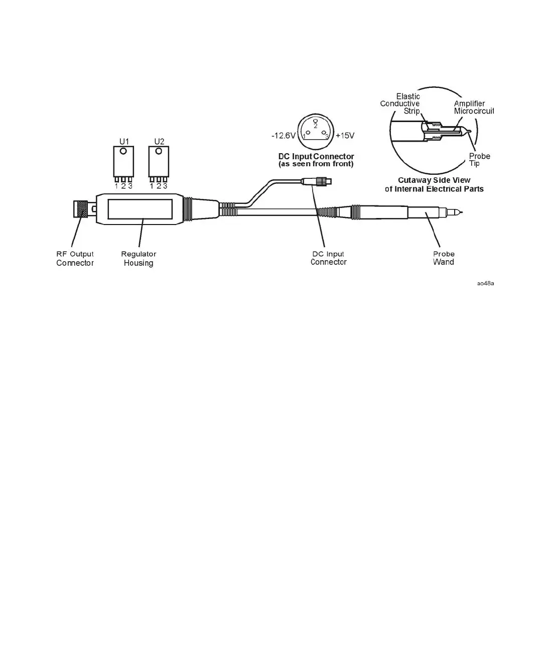
4 Refer to Figure 7-4. Check the +6 V and –4 V power supply voltages on the
exposed portion of the probe end.
If the voltages are good, suspect an amplifier microcircuit failure. Replace the
amplifier microcircuit and do not perform the following steps.
5 If one of these voltages is bad, follow the procedure in “Removing the plastic
regulator housing covers” on page 67, and continue with the following steps.
6 Refer to Figure 7-4. Disconnect the power supply cable and check the
continuity of the three input lines to the A1 regulator assembly. If one of the
wires is broken internally, replace the cable/probe wand assembly.
7 If the three input lines show continuity, desolder the –4 V and +6 V output
wires shown in Figure 7-4. Measure the +6 V and –4 V feedthroughs on the
printed circuit board. If the voltages are good replace the cable/probe wand
assembly. If one of the voltages is bad, troubleshoot the A1 regulator board.
Refer to Figure 7-5 and Figure 7-2 for a component location diagram and
schematic diagram, respectively.