1Overview
14 Keysight E6961A User Guide and Method of Implementation
General Test Setup
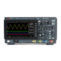
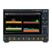
Test Modes 1, 2, 3, and 5 require only the Infiniium oscilloscope and the device to
be tested (Device Under Test or DUT). The test setup is described below.
Differential Signal supplied to the Oscilloscope can be achieved either by using
Two Oscilloscope Channels or a Single Differential Probe. The type of
connection accepted can be selected in the Setup tab of the test application.
Two Oscilloscope Channels refers to connecting the differential automotive pair to
the oscilloscope using only SMA cables. Refer to Figure 1-1 for more details
Single Differential Probe refers to connecting the differential automotive pair to
the Oscilloscope using a single differential probe. Refer to Figure 1-2 for more
details. The only variation would be the Power Spectral Density Level test that
requires a balun.
Any variation from the above definition of differential signalling type is not
recommended
Test Mode 4 requires the N5395C Ethernet Test Fixture and an Arbitrary
Waveform Generator (AWG). Refer to “Test Mode 4. Transmitter Distortion and
MDI Return Loss Tests” on page 34 for specific setup details.
Test Mode 4 also includes an MDI S-Parameter Test. This test is also available as
E6964A BroadR-Reach MDI S-Parameter Software. The E6964A software does
not require the Infiniium oscilloscope.
Test Mode 5 can also use the N9010B Signal Analyzer. Refer to “Test Mode 5.
Transmitter Power Spectral Density (PSD) and Transmitter Peak Differential
Output Tests” on page 42 for specific setup details.
Two Oscilloscope Channels Connection to Oscilloscope
Two SMA cables are needed to directly connect the output of the transmitter to
the oscilloscope. The specific oscilloscope channel used can be selected in the
Configure tab of the application.
An optional TX_TCLK may be supplied to the oscilloscope to run the tests.
 Loading...
