Using the E6960-66600 Frequency Divider Board D
Keysight E6961A User Guide and Method of Implementation 71
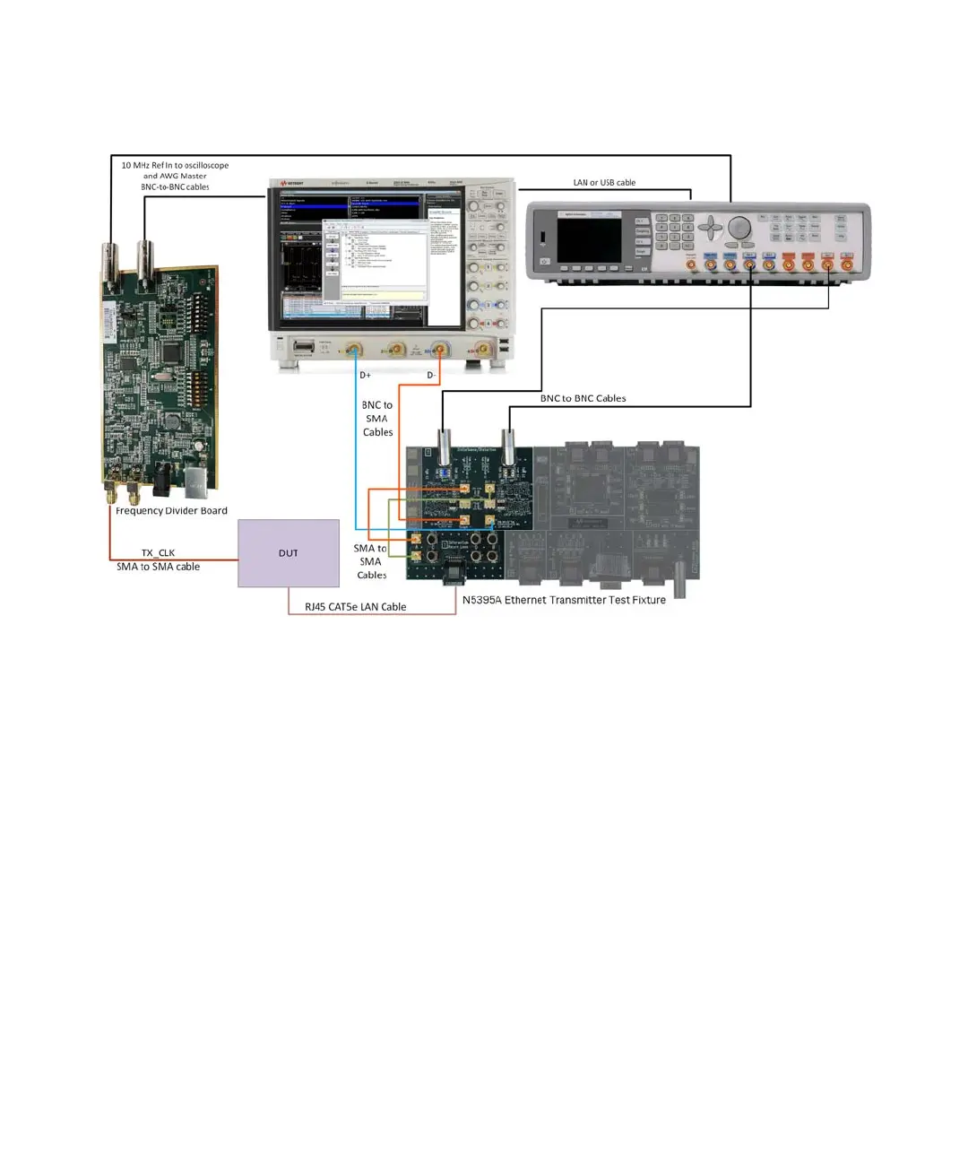
Figure D-3 Test Setup for 10 MHz Frequency Reference
Frequency Divider Board Test Setup
1 Connect CH1 SMA connector to the Device Under Test (DUT).
2 Use BNC to BNC cables to connect both J400 and J403 BNC connectors to
the oscilloscope and the AWG 10 MHz In.
3 Select 4.2 Vpp output voltage by shorting Pin1 and Pin2 of J100 with jumper.
4 Select Normal Running mode by switching switch A1 to OFF.
5 Select Frequency Tracking mode by switching switch A2 to OFF.
6 Select CH1 as input by switching switch A6 to OFF.
7 Select Targeted 25 MHz input by switching switch B2 to ON.