1Overview
26 Keysight E6961A User Guide and Method of Implementation
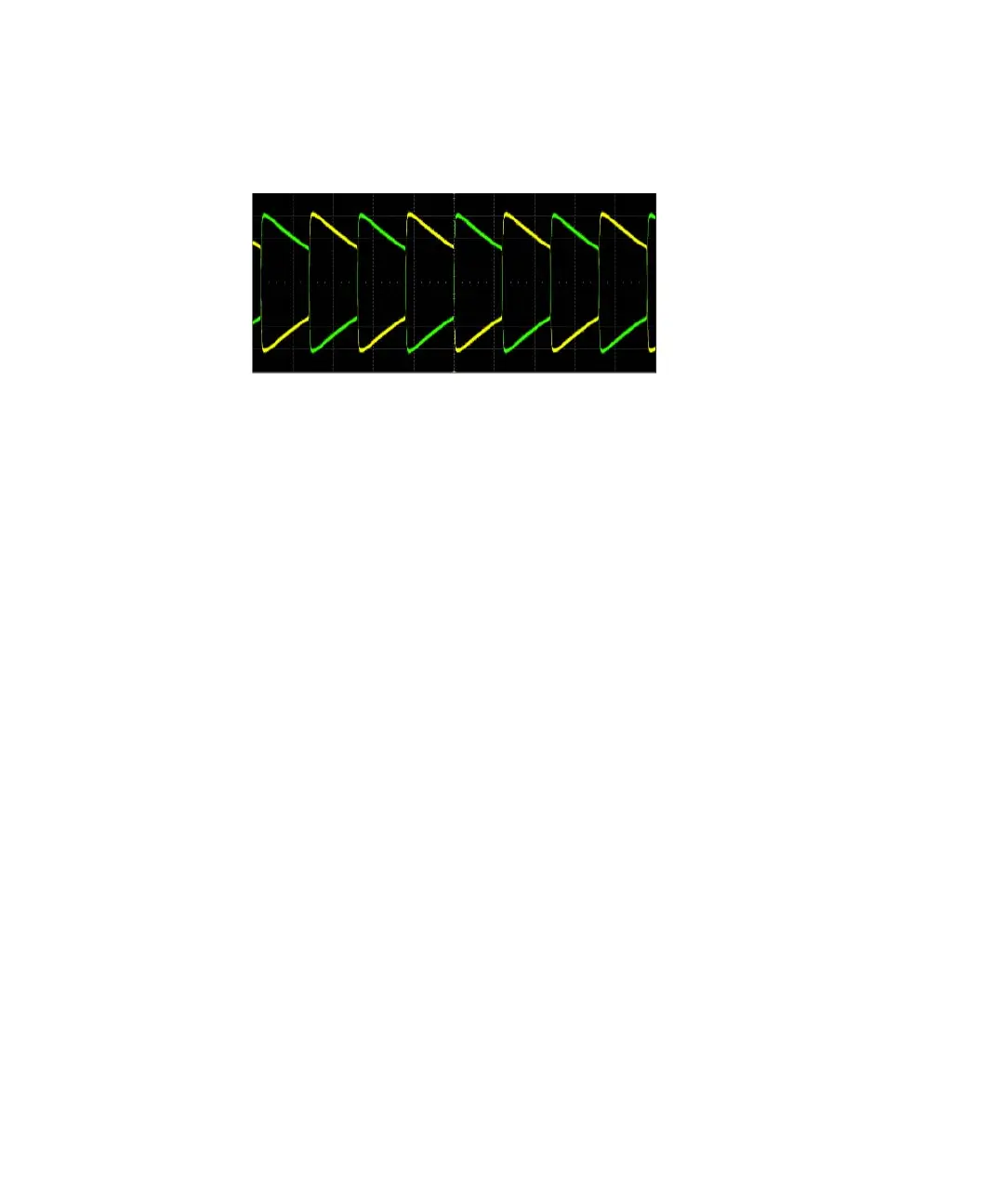
Typical Waveform
Figure 1-10 Typical Positive Droop Test Waveform (using a pair of SMA
cables)
Transmitter Output Droop Negative Test Information
This test measures the negative output droop of the transmitter.
Reference [1] specifies the negative output droop of a compliant PHY. The
negative droop measured with respect to the initial peak value after the zero
crossing and the value 500 ns after the initial peak, shall be less than 45%.
The application triggers the Test Mode 1 signal on the falling edge and
determines the time the negative peak occurred and the voltage at that specific
instance. The application then measures the voltage 500 ns after the peak. The
Droop is calculated as:
Droop = 100 X (Vd/Vpk) %
Where:
– Vd is the magnitude of the droop.
– Vpk is the initial peak after the zero crossing.