Quick Reference 2
Keysight InfiniiVision DSOX1204A/G Oscilloscopes User's Guide 37
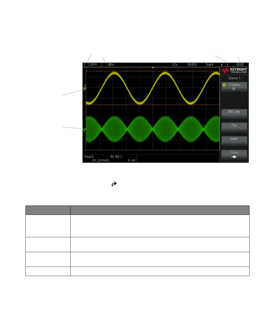
The ground level of the signal for each displayed analog channel is identified by
the position of the icon at the far-left side of the display.
Channel,
Volts/div
Channel 1
ground
level
Trigger
source
Trigger level
or threshold
Channel 2
ground
level
Table 4 Vertical Features
Feature Front Panel Key/Softkey Location (see built-in help for more information)
Channel coupling [1/2/3/4] > Coupling (DC or AC)
Note that Channel Coupling is independent of Trigger Coupling. To change trigger coupling see
"Trigger Mode, Coupling, Reject, Holdoff" on page 51.
Channel bandwidth
limit
[1/2/3/4] > BW Limit
Vertical scale fine
adjustment
[1/2/3/4] > Fine
Channel Invert [1/2/3/4] > Invert
 Loading...


