KICstart Version 1.1.0.x
KICstart User Manual 31
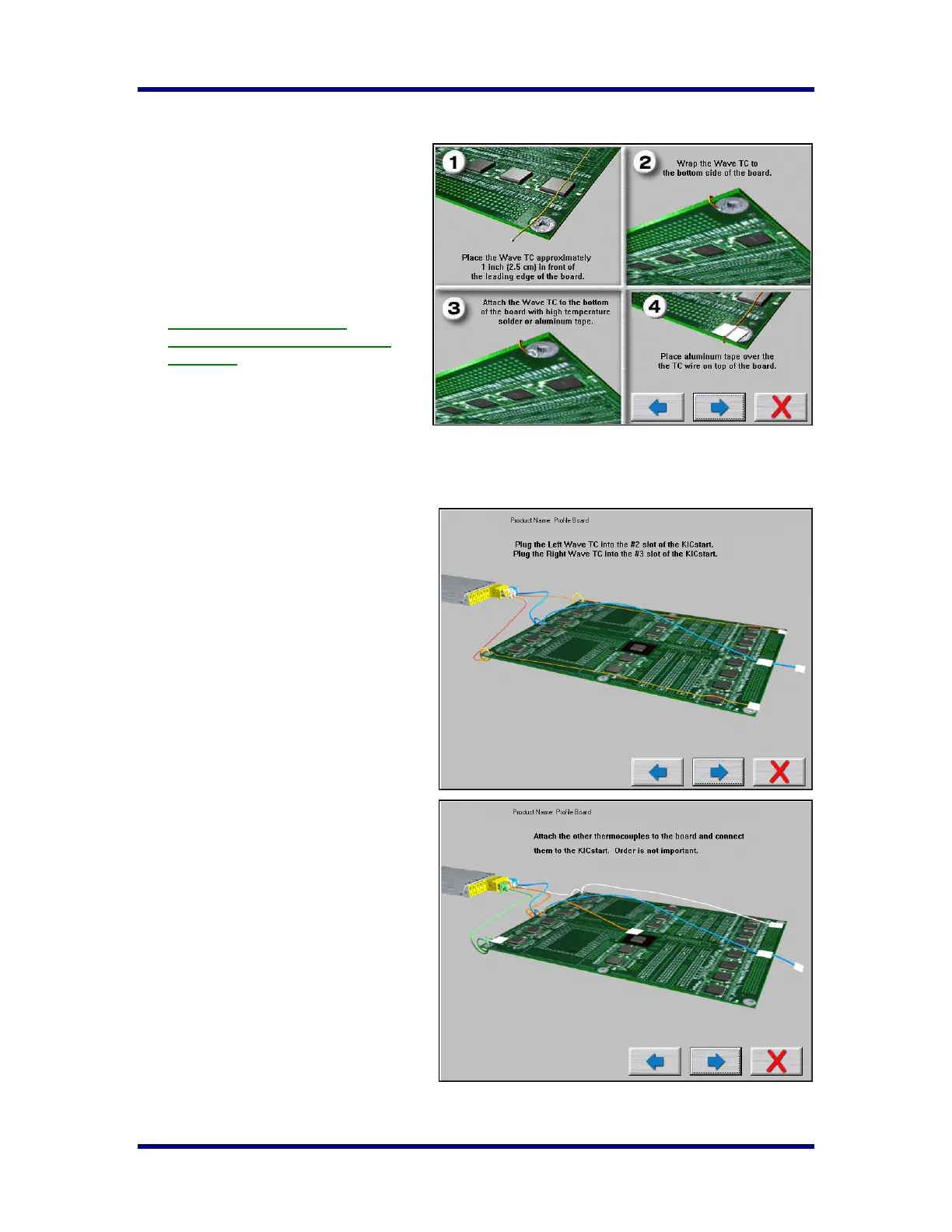
Connecting Wave TCs
The next screen will depict thermocouple
attachment for wave solder profiling. The
KICstart software utilizes two Wave TCs in
addition to the Air TC to collect wave
specific data.
One Wave TC is placed on the Right side of
the board and one on the Left side near the
leading edge of the profile board.
KIC recommend using high
temperature solder to connect both
Wave TCs.
The wave TCs will measure -Wave Dwell
time and Parallelism when profiling a wave
solder machine with the wave on.
Select the Forward Arrow button to continue.
The next screen will depict the placement of
the Wave TCs and instructs what slot/channel
of the KICstart to connect each Wave TC to.
It is very important to follow these
directions.
• Plug the Left-Wave TC into the #2
slot of the KICstart.
• Plug the Right-Wave TC into the #3
slot of the KICstart.
When you have properly connected your
Wave TCs, select the Forward Arrow button
to proceed.
Connecting Product TCs
The next screen will depict placement of the
thermocouples used for profiling the product
(Product TCs). A maximum of three
thermocouples can be used as Product TCs.
Product TCs are connected to the product in
key locations across the product. The
selected locations need represent the highest
and lowest- mass areas of the product or
even specific temperature sensitive
components.
Once you have connected your Product TCs
to your product, connect them to the
KICstart profiler stating with slot #4.
Select the Forward Arrow button to
continue.