J-5 April 200376-100016-002
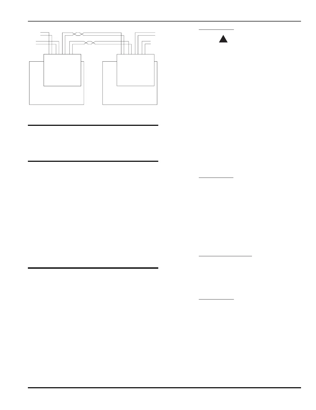
PEGAsys™ LV
B1IA1
B2IA2
B1NA1
B2NA2
NETWORK
INTERFACE
CARD
CCM CPU BOARD
PEGAsys PANEL
PEGAsys PANEL
B1IA1
B2IA2
B1NA1
B2NA2
NETWORK
INTERFACE
CARD
CCM CPU BOARD
Channel 1
Channel 2
All circuits are supervised and power limited.Note:
Figure J-4. Network Wiring
J-5 MAINTENANCE AND/OR REPLACEMENT
No maintenance is required. In the event of failure, the
module should be returned to the factory for repair or re-
placement.
J-6 PARTS LIST
The NIC Installation Kit (P/N 76-100036-500) consists of
the following:
noitpircseDrebmuNtraP
)CIN(draCecafretnIkrowteN005-630002-47
.ni-¾,ffodnatSnolyNni-panS100-241811-60
,ffodnatSssarBsseldaehT23-8
detalplekciN
100-341811-60
.ni-¼1x23-8
rehsaWhtiwwercS
030-611052-60
teehSnoitallatsnI100-848532-60
J-7 INSTALLATION
The NIC is installed as a daughter board to the CCM board.
After this is accomplished, the panels are wired together
using twisted, unshielded-pair cable, AWG-18 or heavier.
For full Style-7 operation, two unshielded, twisted pair
cables must connect each pair of panels, as shown in Fig-
ure J-4. Single-channel operation (using only one twisted
pair cable between NICs) is possible and provides Style 4
operation. With single-channel operation, an open circuit
on any network wire will effectively break the network into
two separate peer-to-peer networks, both functional and
both reporting troubles.
J-7.1
NIC Installation
CAUTION
!
PEGAsys LV system installation applications
require that when a NIC is installed, pre-
discharge and release-state activation, as well
as abort-state activation are limited to the
originating fire-alarm control panel.
Many electronic components are subject to
damage from electrostatic discharge (ESD).
These components are not to be removed from
their protective wrappings until they are to be
installed in their respective equipment
locations, and then only by personnel
connected to earth ground.
Note: For proper network configuration it is necessary
to use Version 8.X (or later) of PCS. For complete
information on this aspect of installation, see the
PEGAsys Configuration Software user's manuals
(P/Ns 76-014 and 76-015). As of this date, Ver-
sion 8.X (or later) of PCS is required for proper
configuration.
J-7.2 Required Tools
Some or all of the following tools will be required to per-
form removal and installation.
• Small flat-blade screwdriver.
• 6" flat-blade screwdriver.
• No. 2 Phillips screwdriver.
• Wire striper.
• Small needle nose pliers.
• Ground strap (wrist strap) for ESD protection.
• IC chip extraction tool.
J-7.3 Central Control Module
The PEGAsys LV panel will be delivered with a separate
network interface card. Following are instructions for in-
stalling a NIC in an existing CCM module. The CCM mod-
ule consists of both the CPU panel and its attached LCD
display and keypad assembly.
J-7.4 Installing a NIC
1. Ensure that all programming is saved using PCS soft-
ware.
2. Put on a properly grounded ESD-protective wrist strap.
3. Remove power from panel but be sure the chassis
remains grounded.
4. Remove four nylon screws holding membrane keypad
and remove membrane by pulling it straight out of its
connector.
5. Remove the six threaded spacers that secure the dis-
play electronics board and lift board out. Do not dis-
 Loading...