J-4April 2003 76-100016-002
PEGAsys™ LV
Refer to Table J-1 for a summary of these relationships.
• Nodes can be added or deleted from network only via
Network Menu.
J-4 FUNCTIONAL DESCRIPTION
This paragraph describes the hardware used to implement
the PEGAsys LV Network:
• Central Control Module (CCM) CPU Board
• Network Interface Card (NIC)
• Network Wiring
J-4.1 Central Control Module CPU Board
The CCM board is a slightly modified version of the origi-
nal CPU board designed so that the NIC will plug in as a
daughter board. This modification has no effect on normal
operation of the PEGAsys LV panel or system.
J-4.2
Network Interface Card (NIC)
The NIC contains the hardware necessary for data-com-
munication between network nodes. The network commu-
nication channels are EIA-485 bus lines. Each node uses
one (1) NIC. The NIC performs the following functions:
• Dual-Channel Support
• Messaging
• Repeater
• Fail Safe
• Isolation
TA1
ISOLATED
NETWORK MEDIUM
TA2
NON-ISOLATED
NETWORK MEDIUM
Hardware
Repeater
Logic
Rx/Tx Selection
Logic
1/2 NETWORK INTERFACE CARD (NIC)
To CCM CPU
TB2TB1
Rx out
Rx out
Tx in
Tx in
Driver
Enable
Driver
Enable
RTS Rx
Tx
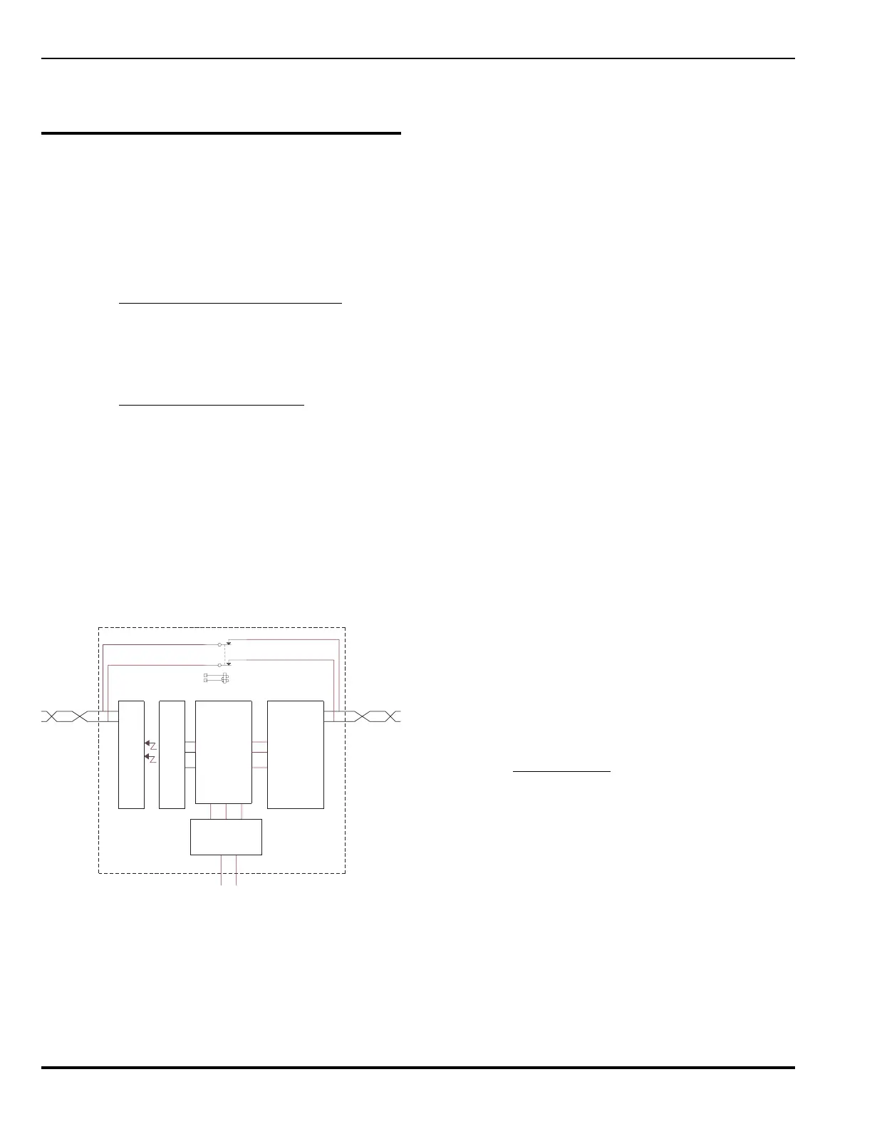
Figure J-3. NIC Block Diagram
(Shown with Power to NIC Lost)
J-4.2.1 DUAL CHANNEL SUPPORT
The NIC supports operation of Style 4 or Style 7 channels.
Under normal operation with Style 7, network communica-
tion is divided between the two channels. In case of a short
circuit or a break in any of the connecting wires, either
channel by itself can execute all network communications,
although somewhat more slowly than if both channels are
in operation.
J-4.2.2 MESSAGING
When a node wishes to transmit over a network channel,
the data is written to the NIC which sends the signals out
to the bus for receipt by remote NICs. While a node is not
transmitting data, the NIC reads the bus data traffic, and
converts it to a form readable by the node’s software. Data
communication will be configured on the NIC’s UART as 8
bits, no parity, 1 stop bit (8-N-1) and 9600 baud. The NIC
will either transmit locally-produced data or receive and
retransmit bus activity as a repeater.
J-4.2.3 REPEATER (TRANSCEIVER)
The NIC acts as a repeater, regenerating bus information
as it moves through the NIC. Its bidirectional repeater func-
tion is implemented completely in hardware; no software
is needed to control this process. The transceiver’s trans-
mit and receive switching (in half-duplex mode) is also per-
formed automatically by hardware.
J-4.2.4 FAIL SAFE
If a power failure occurs in a node, the NIC includes a
normally closed (NC) relay which maintains the communi-
cations integrity of the network. When the NIC loses power,
the relay passes the network signals directly through the
board. While the node without power will not participate in
networking, this pass-through function allows all other net-
work nodes to function normally while providing the proper
trouble indications.
J-4.2.5 ISOLATION
One half of each channel is an isolated, floating RS-485
transceiver and the other half is a non-isolated, grounded
RS-485 transceiver. This assures that the chassis of any
two nodes are physically disconnected, eliminating the
possibility of ground-loop current, while retaining the abil-
ity to detect ground faults.
J-4.3 Network Wiring
The panels are networked by attaching two low capaci-
tance, twisted, unshielded-pair cables between the appro-
priate NICs. The node-to-node wire must not exceed a
length of 4000 ft. and must be AWG 18 or heavier gauge.
Under adverse conditions (for example, high electrical
noise) unshielded, twisted pairs in conduit may be required.
Connect panels together as shown in Figure J-4.
 Loading...