L-2April 2003 76-100016-002
PEGAsys™ LV
The RDCM operator interface needed to enter the pass-
word and access the PEGAsys LV menu is provided via
the alphanumeric keypad:
• 0–9: Used to enter digits to access PEGAsys LV
menus.
• Backspace: Used to exit menu and correct entries.
• Enter: Used when selecting from PEGAsys LV
menus.
Note: Operation of above keys will be hereinafter de-
scribed.
The RDCM and RDM operator interface status LEDs for
monitoring the PEGAsys LV and remote modules are:
• Alarm: Indicates an alarm condition.
• Trouble: Indicates a trouble condition.
• Silence: Indicates PEGAsys LV signal/audibles
have been silenced after Acknowledge.
• Supervisory: Indicates a supervisory condition.
• Power-on: Indicates the system is receiving AC
power.
• Pre-alarm: Indicates a smoke or thermal detector
is in pre-alarm condition.
• CPU fail: Mounted on main PCB and available to
the installer only. Indicates RDCM/RDM proces-
sor has failed to initialize.
LED colors used to represent indications are:
• Red: Alarm.
• Green: Power-on.
• Yellow: CPU failure, trouble, silence, supervisory
and pre-alarm.
The RDM functions as read only. Therefore, it has a scroll
key, but does not provide the other function keys nor an
operable keypad.
L-2.2 Interconnection
The RDCM and RDM operate on a shared RS-485 bus
which supports wire runs of up to 4000 ft. from the PEGAsys
LV control panel. The primary RS-485 bus from the
PEGAsys LV will support up to fifteen (15) RDCMs and
sixteen (16) RDMs in any combination not exceeding the
maximum for each module.
L-2.3 Addressing
Address selection is via setting of the 16-way, 4-bit hexa-
decimal coded rotary switch, SW1, mounted on the printed
circuit board. See Figure L-4.
Table L-1. Address Switch Settings
hctiwS
gnitteS
MCDR/MDR
sserddA
hctiwS
gnitteS
MCDR/MDR
sserddA
110MCDRroMDR9 90MCDRroMDR
220MCDRroMDRA 01MCDRroMDR
330MCDRroMDRB 11MCDRroMDR
440MCDRroMDRC 21MCDRroMDR
550MCDRroMDRD 31MCDRroMDR
660MCDRroMDRE 41MCDRroMDR
770MCDRroMDRF 51MCDRroMDR
880MCDRroMDR061MDR
L-3 OPERATION
Before proceeding with operations, become totally famil-
iar with PEGAsys LV Fire Alarm Control Unit manual, es-
pecially the sections on Active Alarm Mode, Active
Supervisory Mode and Active Trouble Mode. Be sure to
note differences between latching and non-latching Active
Alarm Modes.
For RX/TX loop input devices: To set either latching or
non-latching, refer to the PCS Operations chapter in the
PEGAsys Configuration Software manual.
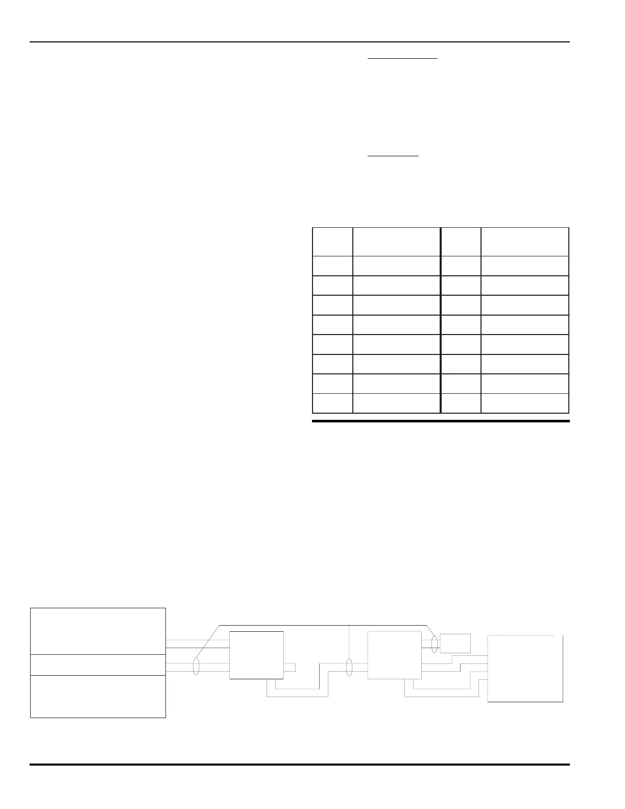
Figure L-3. Interconnection of PEGAsys LV Panel, RDM, RDCM(s)
TWISTED UNSHIELDED CABLE
RDCM/RDM
ASSEMBLY
PIN 1 OF TB1 IS AT TOP OF CONNECTOR
NOTE: ALL CIRCUITS ARE SUPERVISED AND POWER LIMITED
POWER SUPPLY
DCM ASSEMBLY
TB1
PINS
AUX.
+
24V
-
5
6
TB1 PINS
IN
1
8
7
2
ASSEMBLY
RDCM/RDM
TIED TOGETHER WHEN
USING THE PANELS
PINS3&4ARE
POWER SUPPLY
TB1 PINS
OUT
65
4
3
IN
7
8
3
REMOTE
DEVICES
UP TO 31
TB1 PINS
6
1
2
4
5
-
+
AUX. SUPPLY
(IF REQ'D.)
24V
TO TROUBLE
CONTACTS
CLOSED = NORMAL
OPERATION
PEGAsys
76-100016-001