I-27 August 199976-100016-001
Intelligent Suppression Control/Fire Alarm System
PEGAsys
TITLE
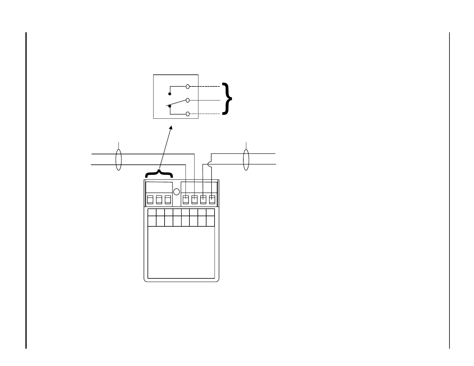
Installation Wiring Diagram
Addressable Relay Output Device
DRAWING No.
New Design
REVISION
-
SHEET
1 of 1
MODEL AO
INSTRUCTIONS
SEE INSTALLATION
CAT. NO. 70-408004-001
SmartOne
TM
FOR SERVICE SEND TO:
KIDDE-FENWAL, INC.
400 MAIN ST.
ASHLAND, MA 01721
DATE OF MANUFACTURE:
MAX. INSTALL. TEMP. 120°F
765
4321
06-235577-001
PC PC PC PC
(+) (-) (+) (-)
N/C
COM
N/O
PC Line
In
(+)
(-)
(+)
(-)
PC Line
Out
See Note 3
N/O
COM
N/C
Field
Connections
TERMINALS 5-7 ARE POWER LIMITED
TERMINALS 1-4 ARE POWER LIMITED
7
6
5
See Note 3
NOTES
1. AO must be installed in the same
room as the device it is controlling .
2. Terminal connection supports wiring
from #18 AWG (0.75 mm
2
) to #14
AWG (1.5 mm
2
)
3. Refer to Control Panel Manual for
addressable loop wiring specifica-
tion.
4. PC Line wiring is power limited and
supervised.