I-26August 1999 76-100016-001
PEGAsys
Intelligent Suppression Control/Fire Alarm System
TITLE
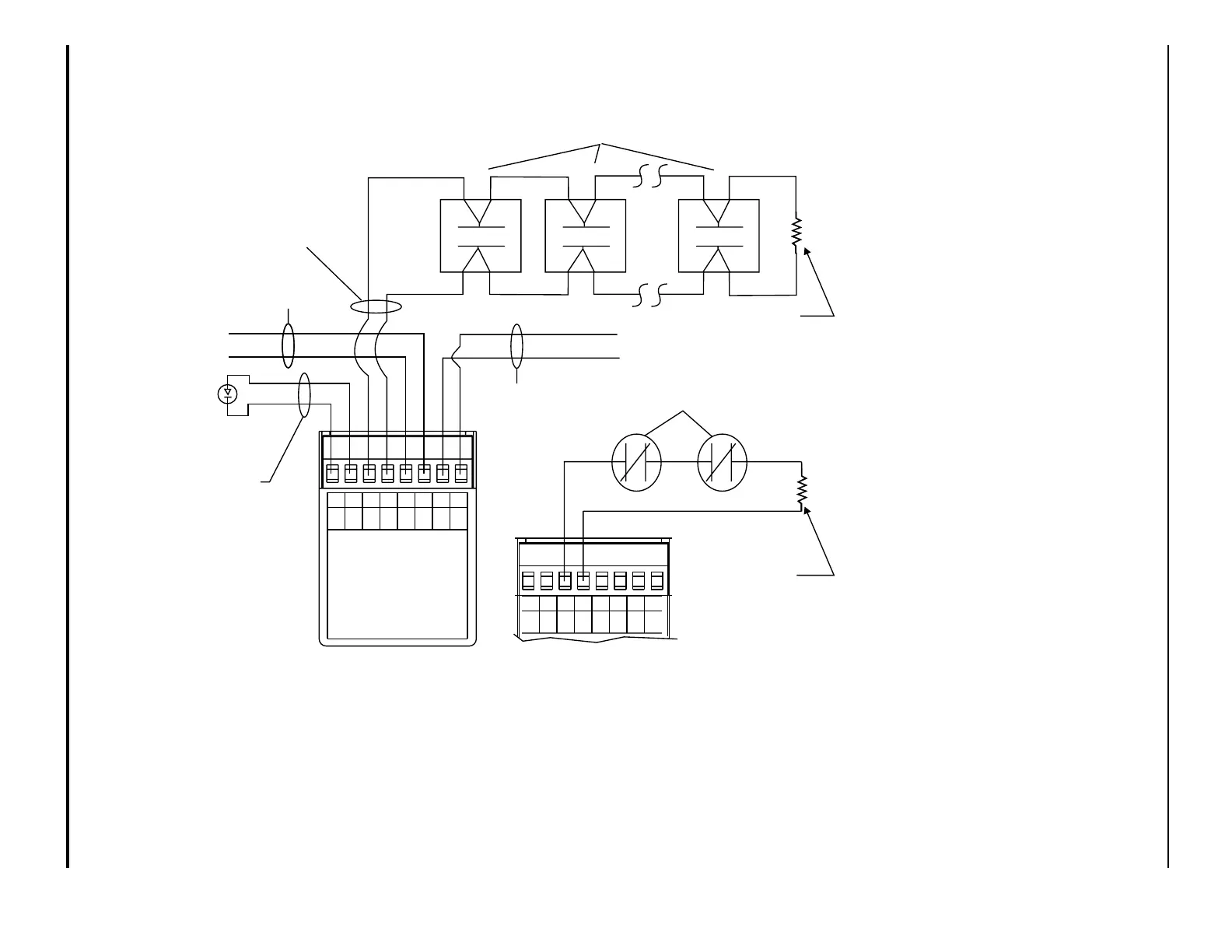
Installation Wiring Diagram
Addressable Contact Input Device
NO/NC
DRAWING No.
New Design
REVISION
-
SHEET
1 of 1
MODEL AI, N/O
INSTRUCTIONS
SEE INSTALLATION
CAT. NO. 70-407008-001
SmartOne
TM
FOR SERVICE SEND TO:
KIDDE-FENWAL, INC.
400 MAIN ST.
ASHLAND, MA 01721
DATE OF MANUFACTURE:
MAX. INSTALL. TEMP. 120°F
7654321
06-235578-001
PC PC PC PC
(+) (-) (+) (-)
8
A
SW
B
SW
(+)
LED
(-)
LED
Remote LED
(Optional)
PC Line
In
(+)
(-)
(+)
(-)
PC Line
Out
EOL
(Listed 10K Resistor)Ω
Typical N.O. Initiating
Devices
See Notes: 1, 2, and 4
See Note 3
Typical N.C. Supervisory
Devices
ALL TERMINALS ARE POWER LIMITED
7654321
PC PC PC PC
(+) (-) (+) (-)
8
A
SW
B
SW
(+)
LED
(-)
LED
EOL
(Listed 10K Resistor)Ω
See Note 3
See Note 7
AI, N/O
AI, N/C
NOTES
1. Maximum 25Ω resistance per wire for
initiating circuit. For a total circuit wiring
resistance of 50Ω max.
2. Terminal connection supports wiring
from #18 AWG (0.75 mm
2
) to #14 AWG
(1.5 mm
2
)
3. Refer to Control Panel Manual for
addressable loop wiring specification.
4. Maximum 10 VDC @ 1 mA.
5. This module
will not support 2-wire
smoke detectors.
6. N/O initiating device circuit is NFPA
Class B/Style B.
7. Rating on LED circuit: 26 VDC Max. 7
mA Max. If not used leave terminals
open circuit.
8. All wiring is power limited and super-
vised.
9. The AI, N/C Device is intended for use
within the control equipment providing
the normally closed contact.
10. The initiating device and remote LED
annunciator (if used) must be located in
the same room as the AI.
11. Use Listed 10K Ohm end-of-line resistor,
P/N 06-129025-003.