1-6Setup PAS SERIES
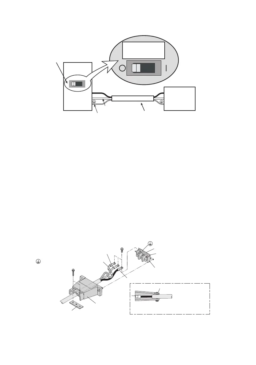
Fig.1-3 Connecting to the switchboard (Example: PAS10-105)
Connection procedure
1. Chec
k that the supply voltage is within the line voltage
ra
nge of the power supply.
Input voltage range: 100 VAC to 240 VAC
Frequency range: 50 Hz to 60 Hz
2. Turn OFF the POWER switch.
3. Connect the provided AC power cord to the AC INPUT ter-
minal board as shown in Fig.1-4.
4. Attach crimp terminals to the AC power source side of the
AC power cord.
5. Turn OFF the switchboard.
6. Connect the AC power cord to match the L, N, and GND of
the switchboard.
Fig.1-4 Connection of the AC power cord on the unit side
PAS10-105
N
L
N
Example:
PAS10-105
Switchboard
(whiteofblue)
L
(blackorbrown)
Examplecircuitbreakerlabel
ForPAS10-105
exclusiveuse
Suppliedpowercord
ForPAS10-105
exclusiveuse
(greenorgreen/yellow)
AC INPUT terminal board
N: White or blue
L: Black or brown
Fastening plate
Fastening plate
(GND): Green or green/yellow
Fix the covered part of the AC power
cord with the fastening plate.
 Loading...