32 TOS5200
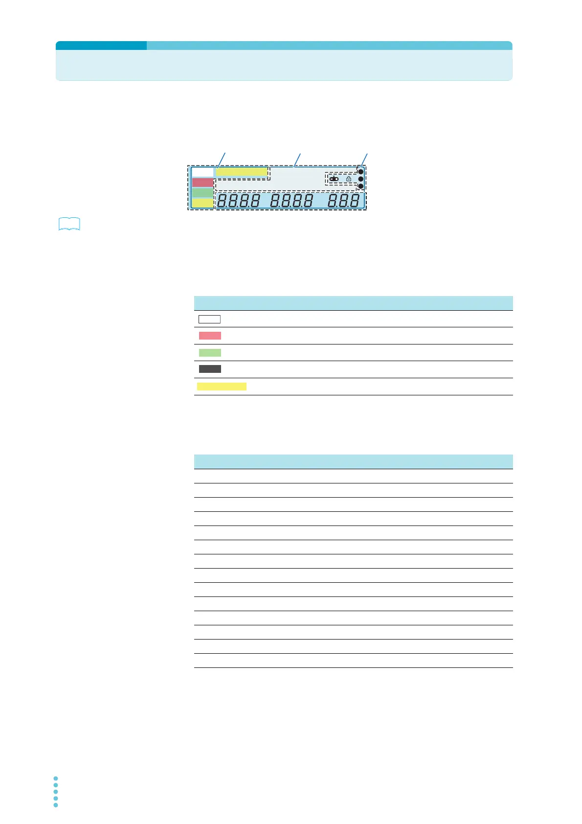
Parts of the Screen
The screen that is used to set the basic test conditions is made up of the four parts shown
below.
p. 72
To reset the TOS5200 to the factory default settings, hold down SHIFT, and turn the POWER
switch on.
Status indicators
These display the status.
Test condition display
This displays test conditions.
A
kV
Mȍ
mA
CONFIG
RISE TEST
RMS AVE MORE CAL RMT
MT
LIMIT
50Hz 60Hz
UPPER
LOWER W COMP
s
1
2
3
READY
TEST
PAS S
FAIL
PROTECTION
Data input
area
Status indicators
Icon areaTest condition display
Display Description
Lights when the TOS5200 is ready to perform a test
Lights when a test is being performed
Lights when a test result is success
Lights when a test result is fail
Lights when a protection function is activated
TEST
PASS
FAIL
Display Description
RMS Lights when the measurement mode is true rms response
AVE Lights when the measurement mode is mean-value response
CONFIG Lights when CONFIG items are displayed
MORE Lights when items other than CONFIG items are displayed
CAL Lights during calibration
RMT Lights when the TOS5200 is being remotely controlled
LIMIT Lights when a limit voltage is set
50 Hz Lights when the frequency is 50 Hz
60 Hz Lights when the frequency is 60 Hz
UPPER Lights when the ammeter is displaying the upper limit.
LOWER Lights when the ammeter is displaying the lower limit.
W COMP Lights during lower limit judgment
RISE Lights when the voltage rise time is displayed
TEST Lights when the test time is displayed