56 TOS5200
SIGNAL I/O Connector
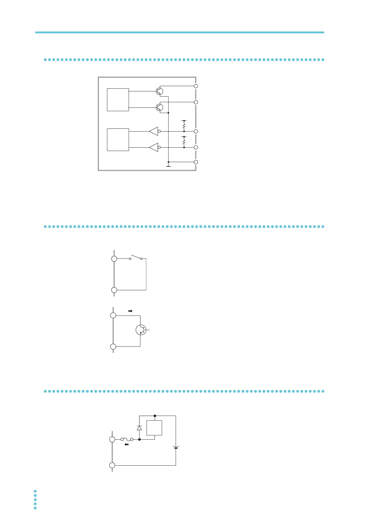
Internal construction
The input signal circuit and the
output signal circuit share the
same common.
The input signals are pulled up to
+15 V. If the input terminals are
opened, the input signal circuit is
put into the same state as when a
high-level signal is applied.
Input signal usage example
Using a make contact to control input
Use a make contact, such as a relay or switch, to set the input ter-
minal to low level.
Using a logic element to control input
Use a logic element, such as a transistor, in place of the switch in
the above example.
Design the circuit so that a transistor collector current (ic) of 5 mA
or greater flows.
Output signal usage example
Driving a relay
Use the output signal to drive a relay.
To improve the safety of the circuit, we recom-
mend that you insert a protection fuse or connect
a diode.
•
•
•
•
•
•
Output
signal
controller
Input
signal
controller
COM
Output signal 1
Output signal 2
Input signal 1
Input signal 2
+15 V
+15 V
Internal construction of the SIGNAL I/
O connector
COM
30 V or
less
400 mA or less
Relay