TOS5200 55
SIGNAL I/O Connector
6
External Control
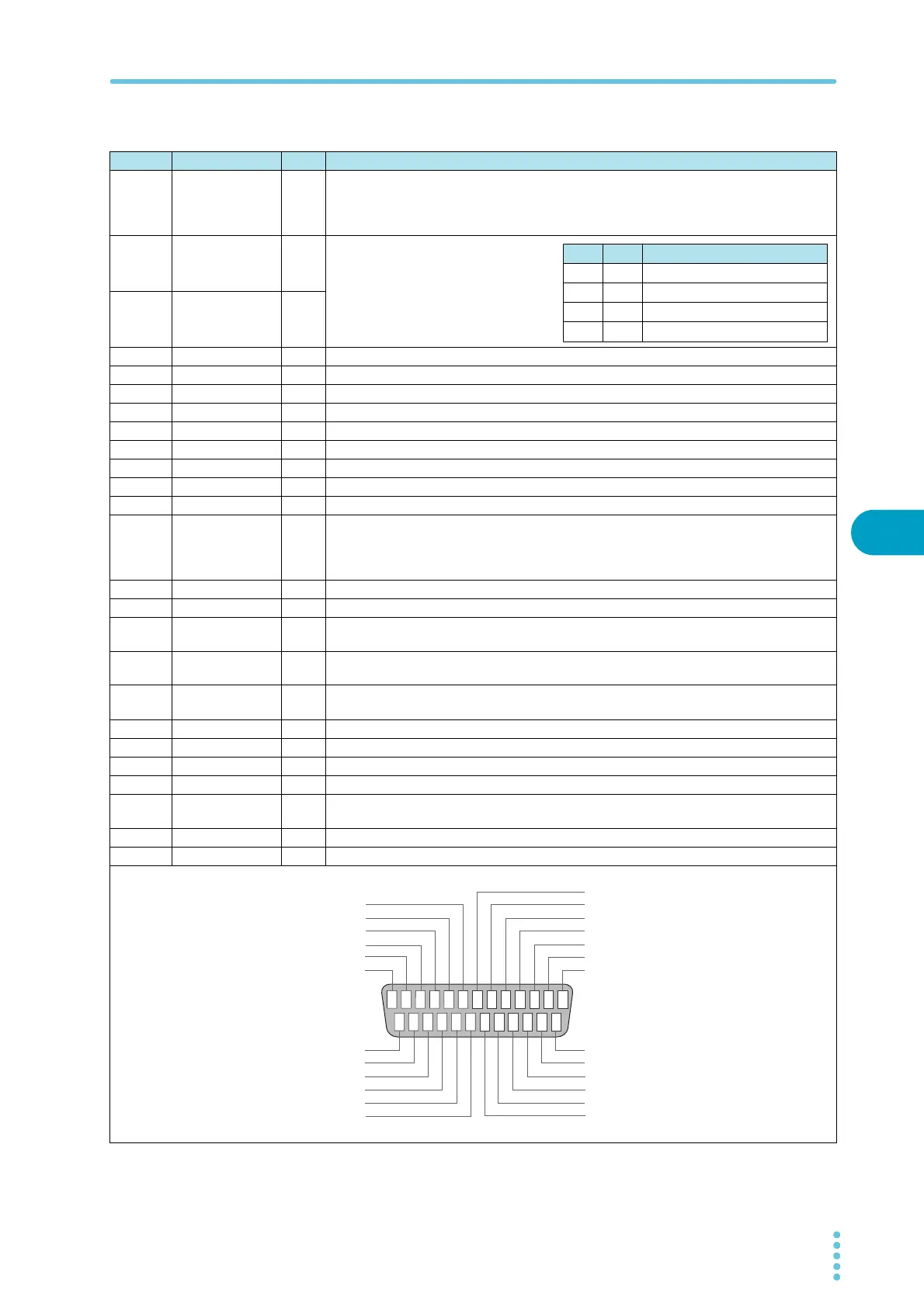
■ SIGNAL I/O connector pinout
Pin no. Signal name I/O TOS5200
1
INTERLOCK+
I
If you open the positive and negative terminals, the output is turned off, and the TOS5200 is
switched to Protection mode.
Open: The resistance between the two terminals is 1.2 kΩ or greater.
Short: The resistance between the two terminals is 1 kΩ or less.
2
PM0
I
Panel memory selection signal.
The selection signal is latched on the ris-
ing edge of the input strobe signal to
recall panel memory.
* The selection of memory is prioritized
over TEST SEL and AUTO SEL.
3
PM1
I
4NC ——
5NC ——
6NC ——
7NC ——
8NC ——
9 STB I Panel memory strobe signal input terminal.
10 TEST SEL I NA
11 AUTO SEL I NA
12 COM — Circuit common terminal.
13
INTERLOCK-
I
If you open the positive and negative terminals, the output is turned off, and the TOS5200 is
switched to Protection mode.
Open: The resistance between the two terminals is 1.2 kΩ or greater.
Short: The resistance between the two terminals is 1 kΩ or less.
14 HV.ON O On during testing and when a voltage remains across the output terminals.
15 TEST O On during testing (excluding when voltage is rising or falling).
16 PASS O
On for at least 0.2 seconds (the PASS HOLD time) when a PASS judgment occurs.
On continuously when the PASS HOLD time is set to HOLD.
17 U-FAIL O
On continuously when an UPPER FAIL judgment occurs because a value greater than or
equal to the upper limit is detected.
18 L-FAIL O
On continuously when LOWER FAIL results from judgment because a value less than or
equal to the lower limit is detected.
19 READY O On when the TOS5200 is waiting (when it is in the READY state).
20 PROTECTION O On when protective features have been activated.
21 START I Start signal input terminal.
22 STOP I Stop signal input terminal.
23 ENABLE I
Input terminal for the start signal’s ENABLE signal. If the ENABLE signal changes, the
TOS5200 is switched to Protection mode.
24 +24 V — +24 V internal power supply output terminal; maximum output current 100 mA.
25 COM — Circuit common terminal.
PM0 PM1 Recalled panel memory number
H H Memory 1
L H Memory 2
H L Memory 3
LL
—
NC
NC
NC
NC
PM1
PM0
INTERLOCK+
NC
STB
TEST SEL
AITO SEL
COM
INTERLOCK-
HV.ON
TEST
PASS
U-FAIL
L-FAIL
READY
COM
+24V
ENABLE
STOP
START
PROTECTION
13
12
11
10
19
18
17
16
15
14
1
2
3
4
5
67
8
9
24
23
22
21
20
25
 Loading...


