TOS5200 59
STATUS OUT connector
6
External Control
How to use the interlock feature
When SIGNAL I/O connector pins 1 and 13 are opened, the interlock feature is enabled.
When the pins are shorted, the interlock feature is released.
When the interlock feature is active, the TOS5200 is in PROTECTION mode. To release the
interlock feature, connect the included SIGNAL I/O plug to the rear-panel SIGNAL I/O con-
nector. Then press STOP to release PROTECTION mode.
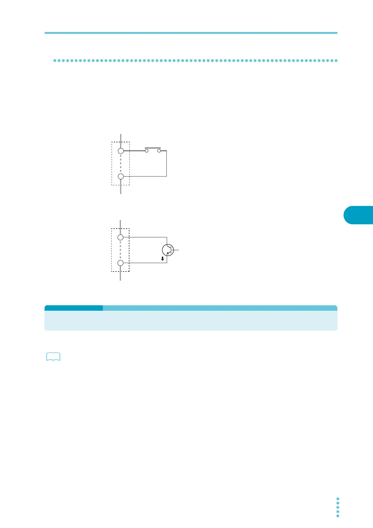
Using an open/close switch
When the contact is open, the interlock signal also
becomes open, and the interlock feature is activated. To
release the interlock feature, close the contact, and then
press STOP or apply a STOP signal.
Use a door switch or other type of switch that has a voltage
rating of 30 Vdc or greater and a current rating of 10 mA or
greater.
Using a transistor or optical device
When the transistor collector current is 5 mA or less, the
interlock feature is activated. To release the interlock fea-
ture, allow an ic of 6 mA or greater to flow, and then press
STOP or apply a STOP signal.
STATUS OUT connector
p. 17 , p. 46
This is the output connector for connecting the optional warning light unit, PL02-TOS.
In CONFIG setting 2, select the status that you want to output. Select H.V ON, Test, Pass,
Upper Fail, Lower Fail, Ready, Protection, or Power ON. If you select multiple items, the sta-
tus that is generated will be the logical sum of the items. When the selected status is true, the
TOS5200 generates a +24 Vdc signal.
For details, see the “WARNING LIGHT PL02-TOS OPERATION MANUAL.”
INTERLOCK
Door switch or
other type of switch
+
–
1
13
INTERLOCK
Photocoupler,
such as a transistor
+
–
1
13
ic
 Loading...


