36
EN
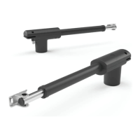
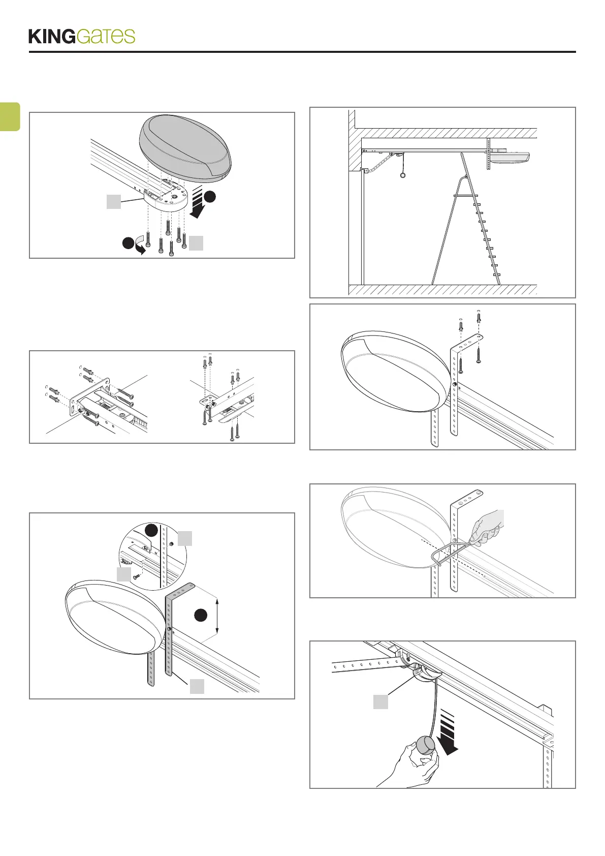
3.2.3 - Fitting the gearmotor to the guide
01. Fit the ROLLS gearmotor output shaft to the guide head [A] and
secure using 4 M6.3x38 screws [G]; (g. 14).
2
1
14
A
G
3.2.4 - Mounting the gearmotor to the ceiling
01. On the basis of distances A, B and C in gures 2 and 3, trace
the two xing points of the front guide bracket at the centre of the
door. On the basis of the type of material, the front bracket can be
xed with rivets, plugs or screws (g. 15). If distances A, B and C
(g. 2 and 3) are sufcient, the bracket can be xed directly onto
the ceiling.
15
02. After drilling the holes in the relative points, leaving the gearmotor
on the ground, lift the guide from the front section and secure using
two screws, plugs or rivets, according to the installation surface.
03. Secure the brackets [H] using the screws [I] and nuts [L], select-
ing the hole most suited to ensure distance B, as shown in g. 16.
1
2
16
H
L
I
B
0÷400 mm
04. Using a ladder, lift the gearmotor until the brackets are touching
the ceiling. Trace the drilling points and then return the gearmotor to
the ground.
05.
06. Drill at the outlined points and then, using a ladder, rest the
brackets against the drilled holes (g. 17) and secure using screws
and plugs suited to the support surface (g. 18).
17
18
07. Ensure that the guide is perfectly horizontal, then cut off the ex-
cess section of the brackets with a saw (g. 19).
19
08. With the door closed, pull the cord to release carriage [M] from
the guide (g. 20).
20
M
09. Slide the carriage until the leaf connecting bracket [N] in g. 21
on the upper edge of the door is perfectly perpendicular to the guide
[O].