44
EN
7. Testing and commissioning
Once the programming setup has been completed, verify that:
- the motors turn off after a few seconds once the opening or closing
phases end (the “error” LED turns off too);
- the control unit responds to the connected wired commands:
“START” (terminal 5), and “STOP” (terminal 6);
- all programmed radio transmitters are operational;
- the safety devices connected to “S2 Photo” (terminal 3) intervene
while the door closes and prevent the open door from closing;
- the safety devices connected to “S1 Edge” (terminal 9) intervene
while the door opens and closes with a brief movement inversion;
If the “Func” dip-switch is put to ON, check that S2 Photo safety
devices intervene also when the door opens and that they prevent
the closed door from opening.
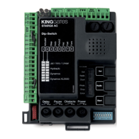
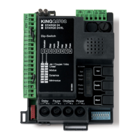
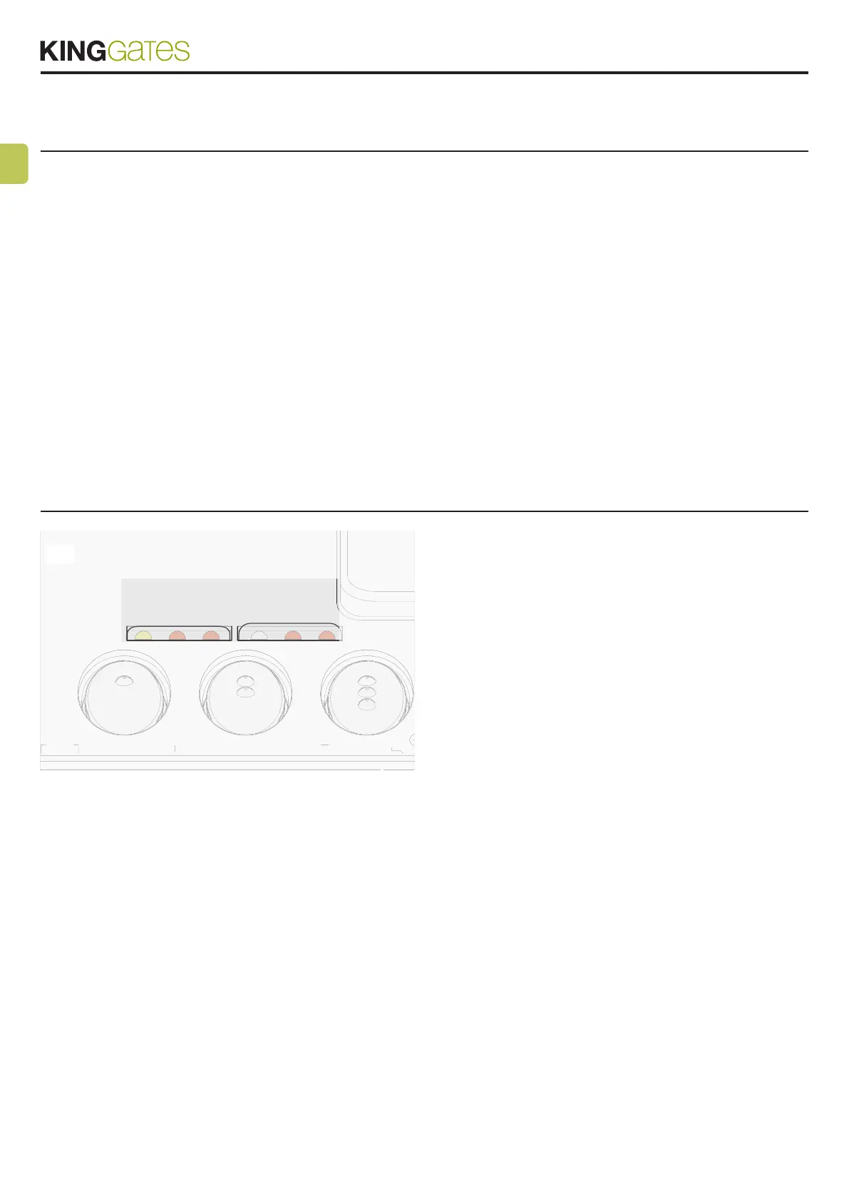
8. LED indication
SET
3
HAZ
4
5
6
7
8
9
10
L
RADIO
Set
Radio
Start
Photo
Stop
Error
START
ET
RADI
TART
With the control unit powered up (if control unit protection is not
activated) the yellow "Set" led ashes briey and, if everything is cor-
rectly connected, the red “Stop” and “SIC” LEDs turn on to indicate
that the three safety contacts are closed circuits.
The yellow “Set” LED is reserved only for programming.
8.1 - Input status LED indication
SIC LED:
- Green: contact S1 Edge (terminal 9) closed and S2 Photo (terminal
3) open
- red: contact S1 Edge open and S2 Photo closed
- yellow: contacts S1 Edge and S2 Photo both closed
- off: contacts S1 Edge and S2 Photo both open
RED START LED:
- on in xed mode if the Start contact (terminals 5-8) is closed
- off if the Start contact (terminals 5-8) is open
36
RED STOP LED:
- on in xed mode if the Stop contact (terminals 6-8) is closed
- off if the Stop contact (terminals 6-8) is opened
YELLOW SET LED:
- is on in xed mode or ashes when the control unit is in a pro-
gramming menu
- is off when the control unit is in out of a programming menu
RED RADIO LED:
- ashes when a command is received through King Gates trans-
mitter
- is on in xed mode when the control unit is in a radio program-
ming menu
- is off when the control unit is in standby mode
RED ERROR LED:
- see paragraph 8.2
RED START LED, RED RADIO LED AND YELLOW SET LED:
- If, when attempting to enter any programming scheme, the “Set”,
“Radio” and “Error” LEDs ash fast three times, it means that
the “control unit protection” is activated. See Paragraph 14.1 for
solving the problem.
8.2 - Error status LED
RED “ERROR” LED:
The red “error” LED has two functions:
- During the automation’s movement, the LED ashes when
a mechanical stress point is detected (this corresponds to
increased motor effort). Adjust FORCE and OBS knobs (slightly
turn them clockwise) to solve this and check gate mechanics
if necessary. Attention: a minimum ash of this LED during the
door movement can be considered as normal.