38
EN
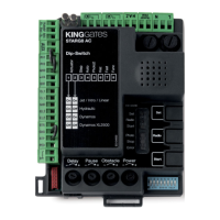
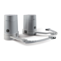
3.5 - Description of the electrical
connections
The following is a brief description of the electrical connections (table
5); for further information, please read section 10 (“Devices connect-
able to the control unit”).
KINGgates s.r.l.
Via A. Malignani, 42
33077 Sacile PN Italy
MODEL
VERSION
Stop
S2 Photo
0 V
Start
24 V
Phototest
Flash
Aerial
1 2
3
4
5
6
7 8 9 10
FORCE
OBST.
PAUSE
START
RADIO
SET
S1 Edge
F 10AL
ROLLS
:
:
Step
ON
Auto
Check
Func
STA
14
13
24 V
8 10
ERR
L
N
SET
RAD
SIC
STP
F 3.15AL
28
Table 5
Terminals Function Description
1 - 2 Flash
24Vdc max. 15W warning light
3 S2 Photo
Input for safety devices, normally
closed contact. Function
associated to dip switch Func
4 Phototest
24Vdc
output for safety
test
5 Start
Start, normally open contact
6 Stop
Stop, normally closed contact
7 0 V Negative terminal for
accessories devices connected
8 24V Power supply
24Vdc
9 S1 Edge Input for safety edges, normally
closed contact. Brief movement
inversion in case of obstacle
during closing and block of the
movement during opening.
10 24V Power supply
24Vdc
L - N Power supply Power supply
230V ac
13 - 14 Aerial Antenna ground (13)
Antenna signal (14)
TIMER FUNCTION: if START contact is kept closed (for
instance through a timer-controlled or bistable relay), control
unit opens the door and leaves the door opened. The automa-
tion does not accept closing commands (neither automatic
nor wired) until START contact is reopened.
In this mode, dip switch 1 STEP is set to OFF and dip 2 AUTO
to ON to ensure that the gate never remains locked open.
If START contact is kept closed during the control unit
starting after a blackout, the door will immediately execute
the start command.
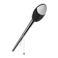
3.6 - Connecting ROLLS to the mains
CAUTION!
- Never cut or remove the cable supplied with ROLLS.
-If not already available, create a power outlet for ROLLS. This
operation must be performed by qualied and experienced
personnel in strict compliance with the current legislation,
regulations and standards
.
ROLLS must be connected to the supply mains by a qualied
electrician.
To test ROLLS, just insert the plug into a power outlet, using an ex-
tension if necessary (g. 29).
29
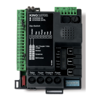
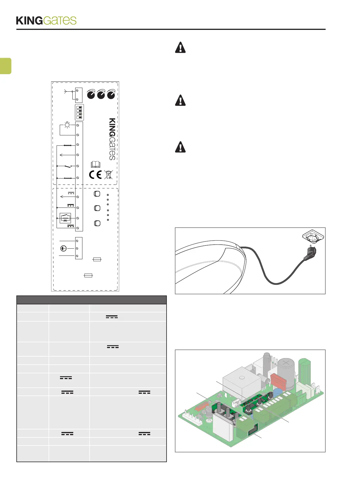
3.7 - Electronic control unit
The following gure (g. 29) the buttons, LEDs, trimmers and dip
switches, which are used for the various congurations, are identied
inside the electronic board.
BUTTON
DIP
CHES
LED
TRIMMER
30