51
The controller HMI Compact or HMI Toutch Panel 4,3`` or 7``
can be connected to the HMI CON port (located in the top
panel of the controller near the USB port) or to the RS485
Master port - if it is not used to transmit information with
the BMS management system. It is possible to connect two
controllers simultaneously, one of them to the HMI CON
port and the other to the RS485 Master port - in this case we
cannot connect the controller from the BMS of the object.
The controller HMI Compact is equipped with a “simple/
ext” jumper, its opening causes the controller to work with
a partially hidden menu, this function will not allow the op-
erator to enter the “service menu”, where we congure the
ventilation system.
The controller menu is always visible in its entirety.
Touch-screen controllers HMI Toutch Panel 4,3` or 7`` HMI
are operated by a controller equipped with an additional
memory card, such a controller is marked with an addition-
al “+” symbol on its label.
The USB connector is used to upload the controller applica-
tion, if the application of the controller does not meet the
requirements of the customer contact the manufacturer
or supplier, it is possible to adapt the application to the
requirements and upload it using any PC class computer.
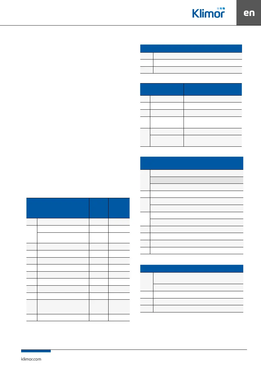
1.3 Standard functions of controller I/Os
Table No. 1 List of digital inputs
Digital inputs (Input NC state – supplying
24VAC to DIN... input switches on the digital
input)
During
correct
system
operation
Lack of re-
quired state
triggers the
alarms
Din 1 Fire alarm system shorted A_AF
Din2
Water heating coil anti-freeze thermostat shorted A_ThHW
Alarm signal of the electric/gas heater
control system
shorted
A_ThHE,
A_ThGAS
Din3 DX chiller alarm signal open* A_CX
Din4 Air supply/exhaust lter pressure gauge open A_Cold_Rec
Din5 Air supply fan pressure guage open A_SupFilter
Din 6 Exhaust lter pressure guage open A_ExhFilter
Din 7 Supply fan pressure guage shorted A_SupPres
Din 8 Defrost signal from the reversing unit shorted A_ DefFunc
Din 9 Supply fan inverter/fan EC EBM alarm shorted A_SupFC
Din 10 Exhaust fan inverter/fan EC EBM alarm shorted A_ExhFC
Din 11
Additional/electrostatic supply air lter
pressure guage (optional)
shorted
A_SupFilter2
or A_SupFil-
terES
Din 12 Service switch/remote start/stop switch shorted A_StopS1
Table No. 2 List of analog inputs
Analog input (0÷10VDC signal )
Ain1 Pressure sensor - supply
Ain2 Pressure sensor - exhaust
Ain3 Air quality sensor CO2, LZO, PM2.5, or PM10
Table No. 3 List of temperature sensors
PT1000 Temperature sensor
Faulty temperature sensor triggers an
alarm which stops the system
PT1 Air supply A_Tsup
PT2 Air exhaust A_Texh
PT3 External A_Tout
PT4
Air exhaust downstream
heat recovery
A_Trec
PT5
Optional leading A_Tmain (when PT5 is selected as the lead sensor)
Return water sensor of
the water heater
A_TbackWater (when the return water sensor
of the water heater is activated)
Table No. 4 List of digital outputs
Digital outputs, switched o state – ReC/ReA output open,
switched-on state – ReC/ReA output shorted
Re1
Water heater pump
Water heater and water cooler pump if H/C water exchanger is activated
Electric heater
Re2 Start of the rotary recovery
Re3
Chiller for water cooler
DX cooler stage I
Re4
DX cooler stage II
Season signal SUMMER (if H/C water exchanger is activated)
Re5 Supply/exhaust air dampers
Re6 Permission to operate electrostatic lters
Re7 Fan operation signal / UV-C lamp control
Re8 Collective alarm signal
Table No. 5 List of analog outputs
Analog output (0÷10VDC signal output)**
Aout1
Heater (water, electric or gas heater equipped with its own power supply
module)
Water heater and cooler (if H/C water exchanger is activated)
Aout2 Cooler (water or DX cooler equipped with its own power supply module)
Aout3 Mixing chamber (10-0V), supply/exhaust air dampers (0-10V)
Aout4 Cross-ow heat/cool recovery
* Possible negation of digital input in Settings/DX cooler menu.
** In the service menu you can select one of the analog outputs as the 0÷10V signal of air
supply fan exhaust fan.
Note!!! Connect the supply and exhaust humidity sensors using modbus
RS485 communication