79
DEC addres Variable
name
Description / Variables Alarms States
Type Read [R]
/Write
[W]
BacNet Modbus BacNet Modbus
394 788
A_Com
SupFC
Alarm for no communication with the supply inverter 0 - no alarm, 1 - alarm present BV
Coil 12608
R
395 790
A_Com
SupFC2
Alarm for no communication with the supply inverter 2 0 - no alarm, 1 - alarm present BV
Coil 12640
R
396 792
A_Com
ExhFC
Alarm for no communication with the exhaust inverter 0 - no alarm, 1 - alarm present BV
Coil 12672
R
397 794
A_Com
ExhFC2
Alarm for no communication with the exhaust inverter 2 0 - no alarm, 1 - alarm present BV
Coil 12704
R
398 796 A_Tsup Supply temperature sensor alarm 0 - no alarm, 1 - alarm present BV
Coil 12736
R
399 798 A_Texh Exhaust temperature sensor alarm 0 - no alarm, 1 - alarm present BV
Coil 12768
R
400 800
A_Tout
Outdoor temperature sensor alarm 0 - no alarm, 1 - alarm present BV
Coil 12800
R
401 802
A_Trec
Alarm of exhaust temperature sensor behind recovery 0 - no alarm, 1 - alarm present BV
Coil 12832
R
402 804
A_TbackWater
Return water temperature sensor alarm from water heater 0 - no alarm, 1 - alarm present BV
Coil 12864
R
403 806
A_Tmain
Leading temperature sensor alarm 0 - no alarm, 1 - alarm present BV
Coil 12896
R
404 808
A_UV_
LampTime
UV lamp operating time overrun alarm 0 - no alarm, 1 - alarm present BV
Coil 12928
R
405 810 A_InEmul Controller input emulation alarm 0 - no alarm, 1 - alarm present BV
Coil 12960
R
406 812 A_OutForce Controller output forcing alarm 0 - no alarm, 1 - alarm present BV
Coil 12992
R
407 814 Alarm Collective alarm 0 - no alarm, 1 - alarm present BV
Coil 13024
R
5.2 Bacnet MS-TP communication with the BMS system
Search for BacNet variables after connecting the switched
on controller and implementing appropriate BacNet net
-
work settings.
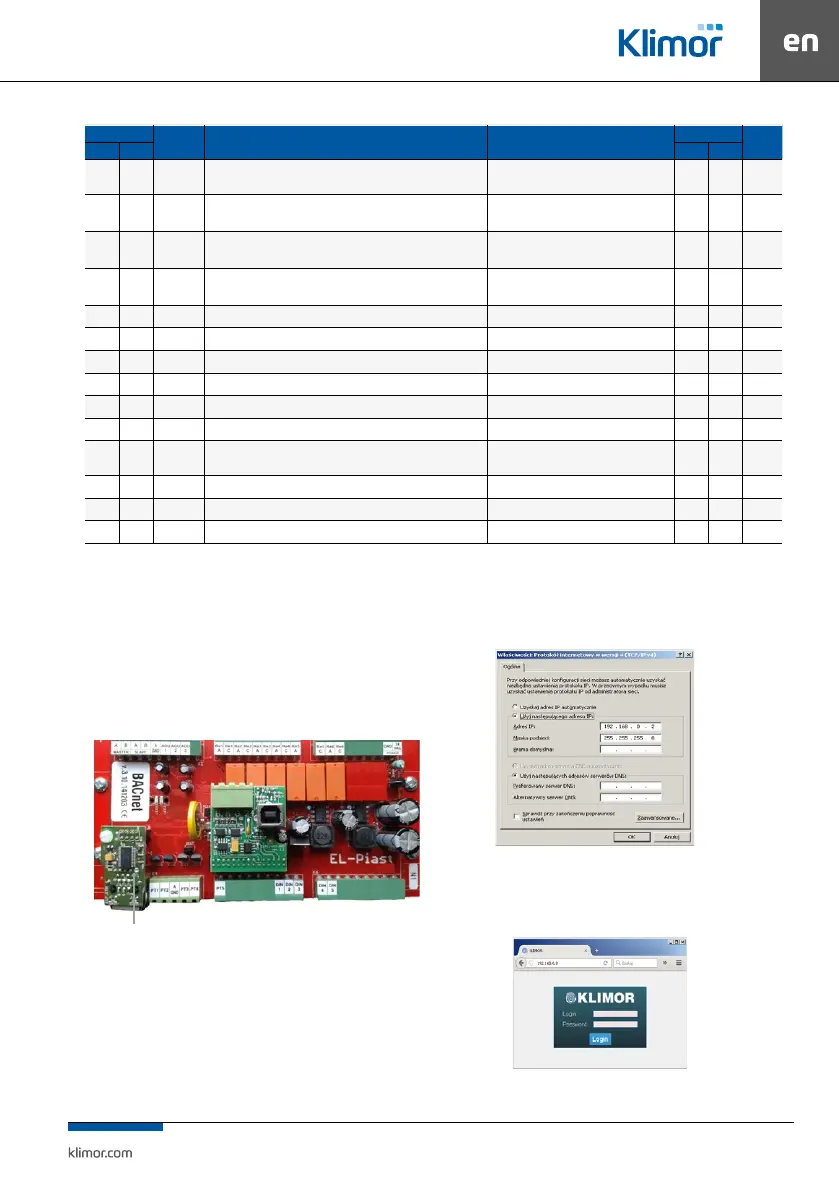
5.3 Control via WWW
The controller can be managed via www protocol.
The shown below optional Ethernet adapter is required as
a hardware element:
Fig. 9 Location for instal ETH module
To connect from a local PC connected directly with ca-
ble with the controller’s ETH adapter:
1. Input the following values in the settings of the PC’s net
-
work adapter for the TCP4 protocol:
Fig. 10 Network module settings of the PC for TCP4 protocol
2. Then open the Internet browser and enter the default
controller address: 192.168.0.8. The window appears
– please enter default login: admin and password: admin
Fig. 11 Login window and access passwords
ETH module with RJ connector