53
3. CONTROL OPERATION
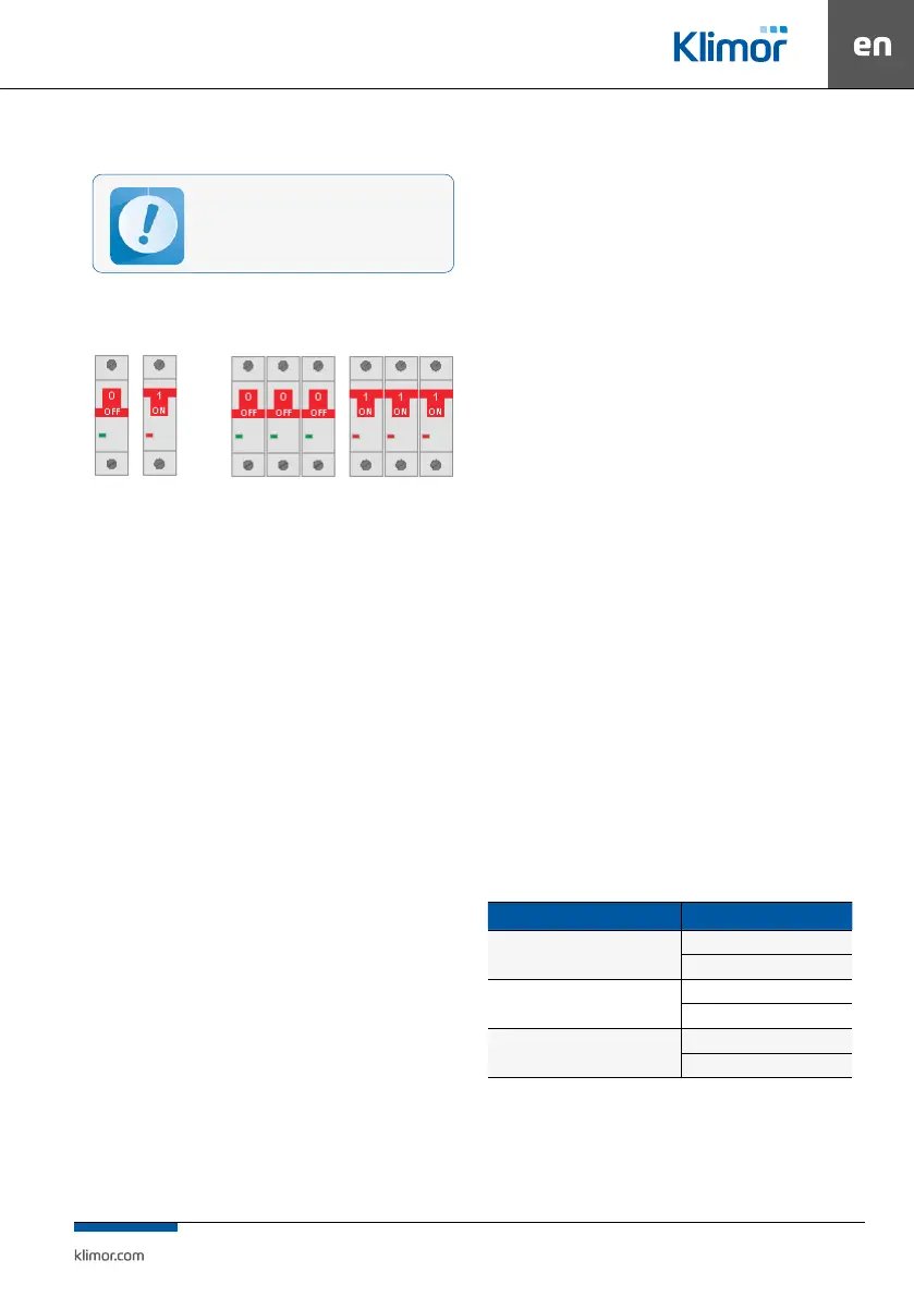
3.1 Starting-up the system
Turn the Q1M trip switch into ON position:
“1-ON” (plastic control unit)
Fig. No
3 Control cabinet switches
In order to start up the system for the rst time:
a) Read this manual and application diagram for a ventila
-
tion system, where the control system is to be applied.
b) Carry out electrical connections in line with the applica-
tion diagram and guidelines listed in this manual.
c) Check, if the sensors and functional elements (actuators,
inverters, etc.) are connected correctly.
d) Turn on the power supply of the control cabinet and set
the application code in the service menu according to the
application diagram (Tab. No 8).
e) Set up the system in the service menu (p.4,4).
f) Deactivate the service mode.
g) In EBM fan systems, set the addresses (when loading
addresses, the EBM fan conguration is performed), so the
above operation should also be performed on all EBM fans
connected to the controller,
h) Turn on the Modbus RTU controller communication with
the EC EBM fans or inverters of air supply and AC air exhaust
fans (if equipped) (p.4.3).
i) Check if the sensor readings and locations are correct.
j) Check operation of the actuators (using Service menu/
output forcing). While testing please pay attention to free
motion of dampers, full open/close state of the actuators.
k) Set the master sensor in “Settings/Temperatures/Master
sensor” menu (p.4.3)
l) Check if any alarms are triggered. If so, they must be
cleared (p.3.4)
m) Start the system (p3.1)
n) Check again if any alarms are triggered. If so, they must
be cleared (p.3.4)
o) Choose the right menulanguage at the controller
Regardless the controller’s factory settings please check the
adjustment of the system in terms of temperature adjust-
ment, cooling the electric heater (if equipped).
Selection of temperature controller settings should be
carried out so that the system introduces the corrections
as soon as possible, without over-regulation (decrease the
Kp parameter and/or increase the Ti parameter in order to
slow down the system response).
Appropriate selection of PI controller settings, operating
the AHU in accordance to performance determined in the
AHU specication sheet, appropriate selection of AHU
components (recommended analog control of each heat/
cool exchanger), system operation at a premise with no
sudden temperature changes due to presence of other
equipment generating high amount of heat/cool, enable
stable control of lead temperature.
In order to check current accuracy of temperature control
please go into “Service menu/Lead temperature history”
(where last 15 measurements of lead temperature sensor
with selected time period are stored) as well as the “Devi
-
ation” is provided, which determines the max. dierence of
current set temperature and last 15 measurements from the
master temperature sensor.
In case of unsatisfactory results of temperature control
process, you have to:
• check if the system operates at its full performance (com
-
pare the frequency of the fan inverters/ compare the
degree of control of the EC motors with the operating
frequency/degree of control given in the panel’s technical
data sheet or with the data obtained from the results of
performance measurements),
• check operation of the actuators and control circuits of the
heaters, coolers and recovery systems,
• check operation of the air dampers,
• check if the temperature sensors are installed correctly,
• check selection of the Pl controllers settings.
Cascade controller – cascading controller in which system
startup is carried out only with the air supply temperature
controller with duration determined in „Settings/Temper
-
ature/Preset temperature ramp” menu, and once this time
passes (if the master sensor is dierent than the air supply
sensor) an additional controller of lead temperature is pro-
vided in order to apply the present temperature setting of
the air supply controller.
Table no. 9 Controller – total of temperature controllers: main, min limit, max limit
Name in menu Factory setting (recommended)
Heating Pl
Kp = 1
Ti = 60s
Cooling Pl
Kp = 1
Ti = 60s
Air supply Pl (air supply Tmin limit, air
supply Tmax limit)
Kp = 1
T1 = 90s
Air supply Pl of the controller can be faster or slower than
heating and cooling Pl. The slower the Pl is, the smaller the
oscillations at min and max air supply temperature but the
reaction to the limit is slower.
Before the user starts the system, the control
cabinet shall be connected and checked by the
authorised personnel.