60
AUTOMATION AND CONTROLLER FOR UNITS EVO-T; EVO-T COMPACT
OPERATION AND MAINTENANCE MANUAL
4.3 Settings
Access to these settings is password-protected (default: 1111).
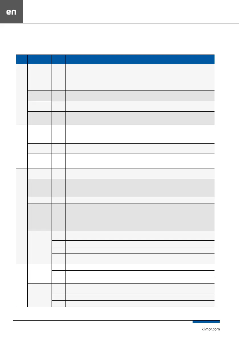
Table no. 12 Settings menu
Group Name
Default
value
Description / Settings menu
Temperatures
Master sensor
Air
supply
Air supply – temperature adjustment according to air supply temperature sensor
Air exhaust – temperature adjustment according to air exhaust temperature sensor
HMI CON – temperature adjustment according to temperature sensor in the HMI programming device connected to the HMI CON connector
HMI RS485 – temperature adjustment according to temperature sensor in the HMI programming device connected to the RS485 connector
PT5 – temperature adjustment according to temperature sensor connected to the PT5 sensor input
Auto – temperature adjustment according to temperature sensor of the air supply section (in winter) and air exhaust section (in summer)
Eco temperature
dierence
15°C
This function is used both for heating and cooling; it prevents from heating/cooling when external temperature is higher/lower by set value
than air exhaust temperature sensor (this function is active only in air supply-exhaust systems)
Start ramp
600 s
Start ramp – drop time of increased requested temperature in systems with water heater and delay of switching on the cascading tem-
perature controller
Correction
of requested
temperature
5°C Correction of set temperature – set point of set value increase and air supply min temperature at the system start
Season
Operation mode
Auto
Important option for the master sensor in Auto mode and for the H/C water exchanger
Auto – year season determined automatically based on the external temperature sensor
Winter – manual set point of winter operation mode
Summer – manual set point of summer operation mode
Temperature –
summer
20°C
Temperature – summer – the external temperature threshold setting above which the system operates in the summer mode, the leading
sensor (set in auto mode) is the air exhaust sensor and the HPM/CM module and H/C water exchanger can operate in cooling mode
Hysteresis
4°C
Hysteresis – the hysteresis setting for the „Summer.temp” threshold, the external temperature drop below the dierence between the
„Summer.temp” and „Hysteresis” makes the system operate in winter mode, the leading sensor (set in auto mode) is the air supply sensor
and the HPM module can operate in heating mode.
Standby mode
Temperature
setting
22°C
Temperature setting – set temperature settting of the standby mode master sensor, (however temperature adjustment is carried out according to the
master temperature sensor and temperature set point from the main menu)
Standby master
sensor
HMI CON
Air exhaust – switching on the system according to the air exhaust temperature sensor
HMI CON – switching on the system according to the air exhaust temperature sensor in the HMI programming device connected via HMI CON
HMI RS485 – switching on the system according to the air exhaust temperature sensor
PT5 – switching on the system according to temperature sensor connected to the PT5 sensor input
Lead sensor ...°C Lead sensor – temperature reading from the leading standby sensor
Active for
Heating
and
cooling
Heating – system is started, when the standby mode master sensor temperature drops below the set standby temperature by the standby
hysteresis value
Cooling – system is started, when the standby mode master sensor temperature exceeds the set standby temperature by the standby
hysteresis value
Heating and cooling – system is started, when the standby mode master sensor temperature drops below or exceeds the set standby
temperature by the standby hysteresis value
Standby hysteresis
4°C
A dierence between the standby temperature sensor and the set standby temperature above which the system is activated while operating
in the standby mode
10 s Switch on delay – time between starting the dampers and starting the fans.
30 s Pressure gauge delay – time from starting the fans after which lter pressure is measured.
30 s
Cooling down time – the time from switching the operating mode „Operation 1,2,3 gear” to the operating mode „Stop” and stopping the
operation of the electric heater, gas and/or DX cooler to stopping the fans. In the case of a gas heater, enter the OMM setting of the gas module
Fans
-
10 s Switch on delay – time between starting the dampers and starting the fans.
0 s Dampers shutdown delay – time from the fan stops to the dampers stop
30 s Pressure gauge delay – time from starting the fans after which lter pressure is measured.
Cooling down time
30 s
Cooling down time – the time from switching the operating mode „Operation 1,2,3 gear” to the operating mode „Stop” and stopping the
operation of the electric heater, gas and/or DX cooler to stopping the fans. In the case of a gas heater, enter the OMM setting of the gas module
100% Air supply – air supply fans capacity during cooling down
100% Air exhaust – air exhaust fans capacity during cooling down
 Loading...