89
7. HE ELECTRIC HEATER CONTROL MODULE
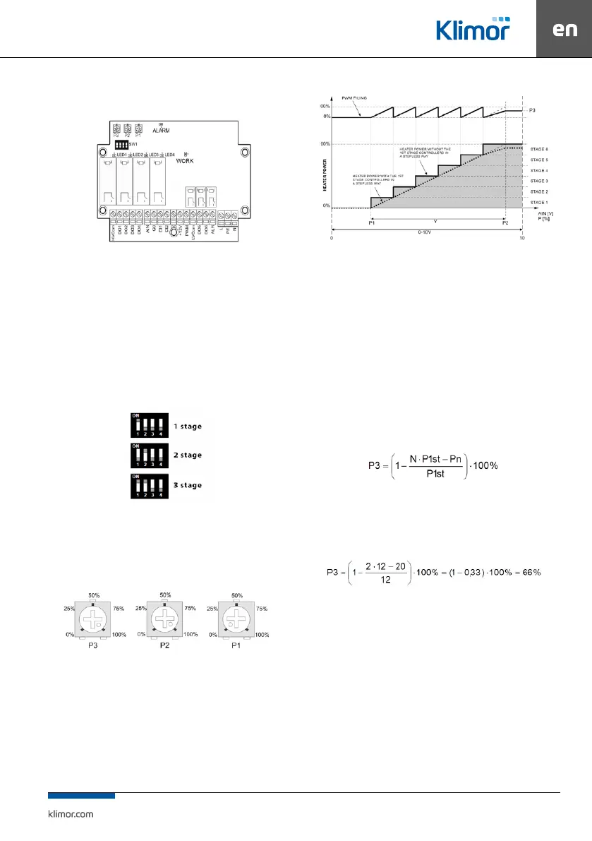
Fig 36 The module controlling the electric heater
The HE module can be congured individually depend-
ing on the need for power of the tted electric heater.
If it is not necessary to use full power of all heating stag-
es it is possible to switch o any number of the heater sets
or partially limit the stage controlled with the use of sol
-
id-state relays.
The number of activated stages of the heater is set
by the dip-switch type switch installed on the PCB in
accordance with the following conguration:
Fig. 37 Setting of heater stages
Additionally it is possible to limit the max adjustment value
for the PWM signal of the SSR relay. They are controlled by
means of changing settings of the P3 pot.
Fig. 38 Potentiometers settings
The P1 and P2 pots enable narrowing down the system op-
eration range in relation to the full 0÷10V signal scale. This
solution enables the application of one 0÷10V signal to con
-
trol two multistage electrical heaters.
The N=P2-P1 dierence cannot be smaller than 10% for each
selected heating stage (e.g. for 1 level: N ≥ 10%, for 6 levels:
N ≥ 60%). If due to the pots setting the N dierence is lower
than the required value, then the system triggers an alarm.
Fig. 39 Workow of heating adjustment
Sample module setting:
The 3-stages P=36kW (12kW/stage) electric heater is tted.
The rated heating power required to heat the building is
Pn=20kW.
As standard the module is supplied in a conguration ena
-
bling usage of the max. heater power. The rst step is to de-
ne the min. number of operating stage of the heater. The
sum of power values of active stages must be higher or equal
to the Pn power. In our case the power of 2 stage is sucient.
The dip-switch should be set to the position of stage 2.
Then you should calculate the PWM limit value in accord
-
ance with the following formula:
where:
P3 – calculated PWM signal limit
N – number of activated stages
P1st – power of a single stagel of the heater [kW]
Pn – power required for the building [kW]
By substituting into the formula:
The P3 pot should be set to 66%.
First start-up
• Read this manual as well as the AHU control system manual.
• Check and start the AHU control system, and then connect
power supply and control of the HE module as well as power
supply of the heat output stages, in accordance with the
AHU application diagram and the HE module diagram.
• Switch on power supply of the AHU control cabinet and the
HE module.
• Set a number of heater levels at the HE module controller
• Check operation of the system.