80
AUTOMATION AND CONTROLLER FOR UNITS EVO-T; EVO-T COMPACT
OPERATION AND MAINTENANCE MANUAL
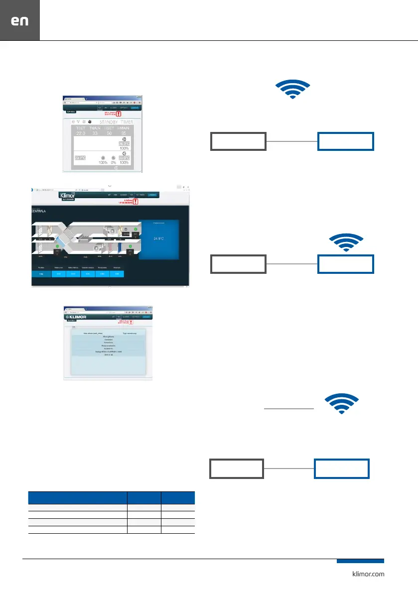
3. When the login and password are entered and the login
is validated, the controller’s HMI screen appears. Here you
can change the settings and view all controller menu op
-
tions.
Fig. 12 Controller HMI graphic screen
Fig. 13 AHU visualisation screen
Fig. 14 Controller HMI screen
4. The controller has Ethernet interface so in order to con-
nect the controller in wireless mode with local wireless
network (WIFI) please use an additional router – congure
a local WIFI network as a access point and then connect the
controller to the router. The network settings of the rout
-
er and controller must be matched properly. Forward the
ports to the router external address.
5.4 List of EVO-T inverter addresses
1
Tab. Nr 19 Addresses of modules and components controlled via RS485 in EVO-T
Element Adress DEC Adress HEX
Supply fan inverter 1 21 15
Supply fan inverter 2 22 16
Exhaust fan inverter 2 32 20
Exhaust fan inverter 3 33 21
Examples of connection methods are shown below:
1. Connecting the controller to a local network via WIFI
Fig. 15 Connecting the controller to a local network via WIFI
Router with port forwarding: 80 from the ELP controller, i.e.:
192.168.0.8:80 to the router external address: 10.10.10.31, so that
we can see the ELP controller in the local WIFI network. Access to the
controller is provided via http://10.10.10.31
2. Direct communication with the controller via the WIFI Router
Fig. 16 Direct communications with the controller via the WIFI Router
Router with port forwarding: 80 from the controller, i.e.: 192.168.0.8:80
to the router external address: 192.168.0.1, so that we can see the con-
troller in the local WIFI network. Connecting with a dedicated router
network enables access to the controller via http://192.168.0.8
3. Connecting the controller with the local WIFI network with
external sharing
Port forwarding at the main router from the controller’s WIFI
router: port: 80 with IP: 10.10.10.31 to the external IP: port 80 IP:
83.100.100.1
Fig. 17 Connecting the controller with the local WIFI network with external sharing
Router with port forwarding: 80 from the controller, i.e.: 192.168.0.8:80
to the router external address: 10.10.10.31, so that we can see the con-
troller in the local WIFI network. Connecting with any Internet connec-
tion enables access to the controller via http://83.100.100.1
LOCAL WIFI NETWORK
np. 10.10.10.1
PLC
ROUTER
192.168.0.8
Default address
192.168.0.1
Subnet address
WIFI network address
10.10.10.31
PLC
ROUTER
192.168.0.8
Default address
192.168.0.1
Subnet address
LOCAL WIFI NETWORK
e.g. 10.10.10.1
PLC
ROUTER
192.168.0.8
Default address
ISP
Static IP:
83.100.100.1
192.168.0.1
Subnet address
WIFI network address
10.10.10.31