85
6.2 HMI touch control panel TP4,3`` or HMI TP7``.
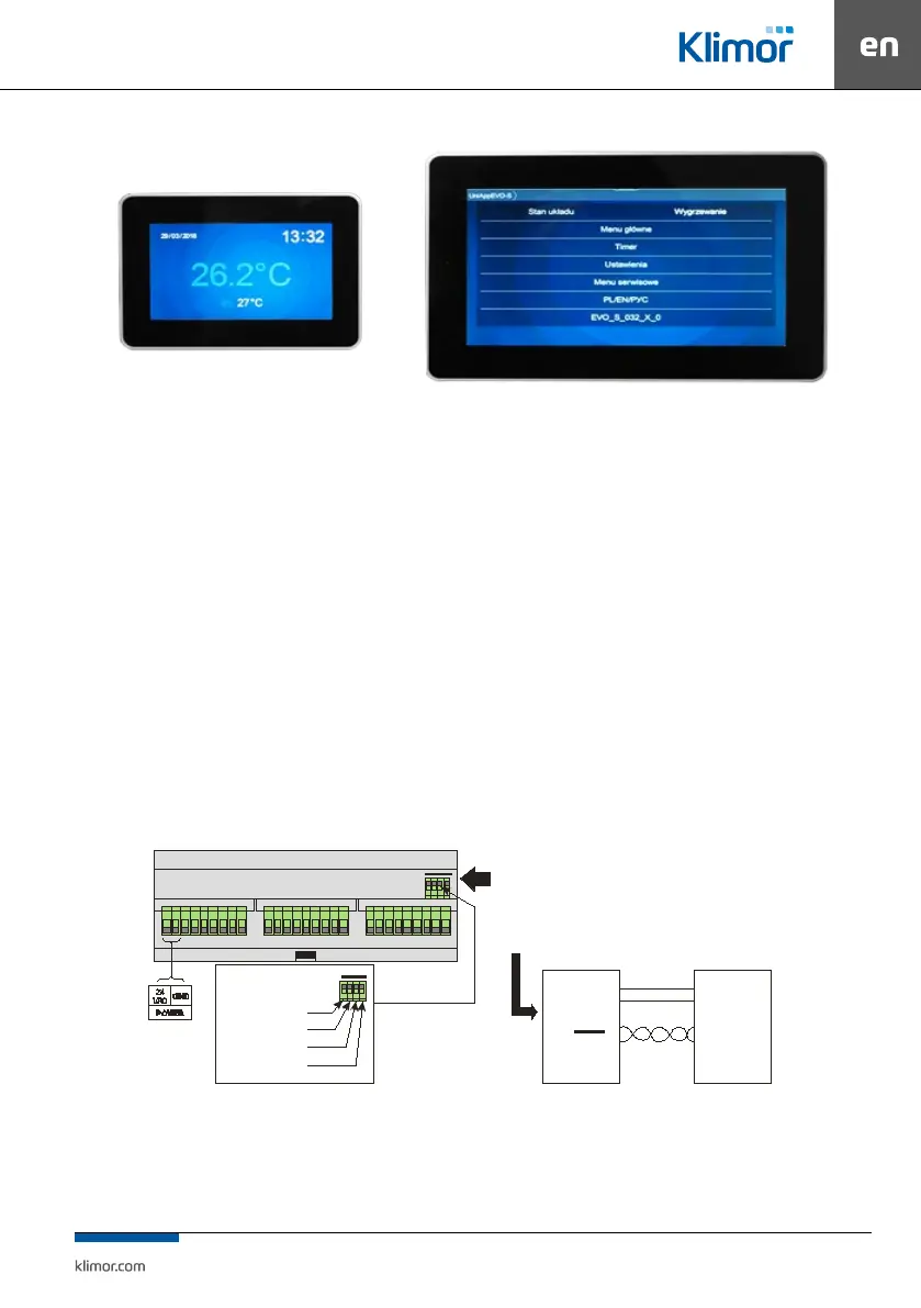
Fig. 27 Panel HMI TP 4,3” or HMI TP 7"
6.2.1 Technical data
HMI TP4,3”
• Power supply voltage: 24 V AC/DC +/- 10%
• Power consumption max.: 2,5W
• Power consumption in stand-by mode: 1W
• Display resolution: 480x272 px
• Colour depth: 18 bit
• Touch panel: capacitive multitoutch
• Communication connection: RS 485
• Cooperation with ELP... series controllers
• BACnet MS/TP or Modbus protocol
• Built-in temperature sensor
• Temperature in operation mode: +10 … 40°C
• Storage temperature: -20 … 70°C
• IP Protection rating: 30
• Dimensions: 126 x 87 x 16 mm
HMI TP7”
• Power supply voltage: 24 V AC/DC +/- 10%
• Power consumption max.: 3W
• Power consumption in stand-by mode: 1,2W
• Display resolution: 800x480 px
• Colour depth: 18 bit
• Touch panel: capacitive multitoutch
• Communication connection: RS 485
• Cooperation with ELP... series controllers
• BACnet MS/TP or Modbus protocol
• Built-in temperature sensor
• Temperature in operation mode: +10 … 40°C
• Storage temperature: -20 … 70°C
• IP Protection rating: 30
• Dimensions: 193 x 125 x 16 mm
1: 24 Vac
2: GND
3: + RS485 - A
4: - R S485 - B
24 VAC
GND
A
B
VA C
GND
A
B
Sterownik PLC
HMI Advance
W sterownikach z serii ELP... jest możliwość
podpięcia HMI do specjalnego złącza HMI CON.
Standardowo w każdym sterowniku jest
HMI CON
6.2.2 Diagram of connection of HMI to the controller
Fig. 28
In the ELP... controllers it is possible to connect the HMI to a
special HMI CON connector.
As standard, each ELP controller has
PLC Controller