64
AUTOMATION AND CONTROLLER FOR UNITS EVO-T; EVO-T COMPACT
OPERATION AND MAINTENANCE MANUAL
4.4 Service menu
Access to these settings is password-protected (default: 1111).
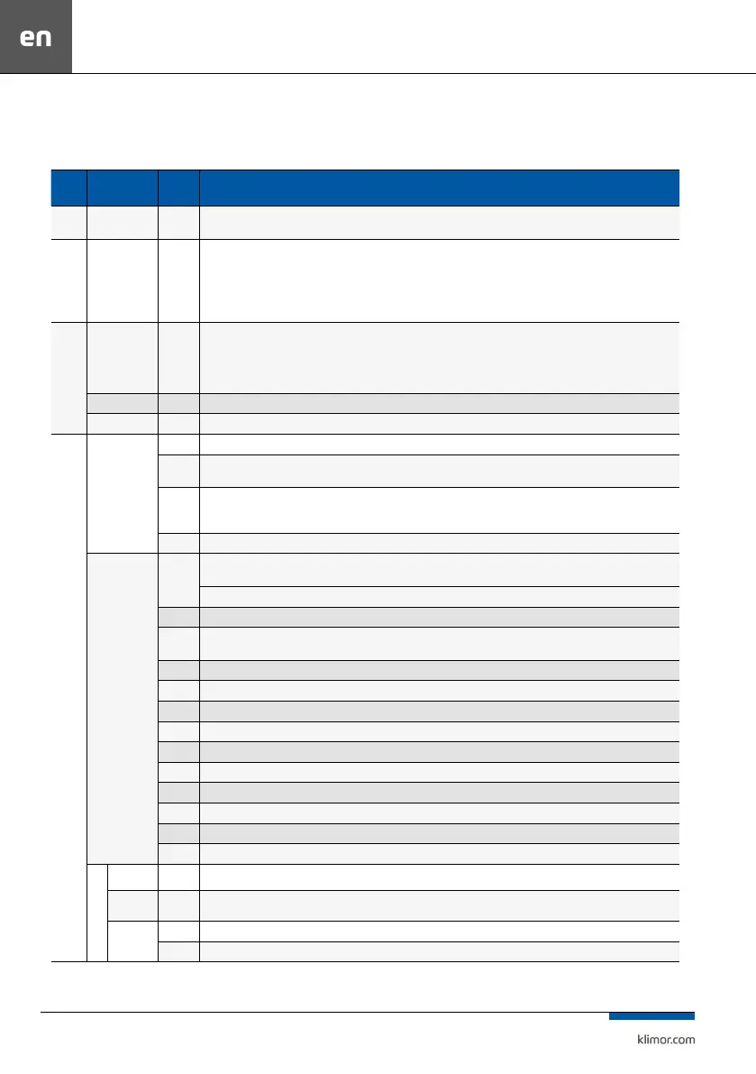
Table no. 13 Service menu
Name Name
Default
value
Description / Service menu
Service
mode
- Active
Active – possible system set up, it is not possible to start the system, activated protection functions of selected system
Inactive – it is not possible to set up the system, the system can be switched on
Ope-
ration
mode
- o/on
o/on – active operation mode OFF/ON
o/1/2/3 – active operation mode OFF/Speed1/Speed2/Speed3
o/1/2/3/T – active operation mode OFF/Speed1/Speed2/Speed3/ Timer
o/1/2/3/S/T – active operation mode OFF/Speed1/Speed2/Speed3 / Standby / Timer
Note!!! Operation for settings on the TP4,3 and TP7 graphical touch panel menus is available in o/1/2/3/S/T mode, in other modes only the
simplied „saver” graphic screen invisible.
AHU
type
Type SCS
SCS – air supply AHUs
SECS – air supply-exhaust AHUs
RGCS – air supply-exhaust AHUs with glicol recovery
PRCS – air supply-exhaust AHUs with cross-ow plate heat recovery equipped with bypass
RRCS – air supply-exhaust AHUs with rotary heat recovery
Application code 0 A setting of the code consistent with coding described in the point 4
Code consistency Correct Code consistency check, if not consistent it is not possible to start the system and the A_Code alarm message is displayed
The set
up
Temperature
- Oset – the possibility to adjust the measuring points from temperature sensors
-
A_LowTemp – System operation locks function, when the fans operate too long at low air supply temperature.
Possibility to activate/deactivate the function, min. air supply temperature setting, low temperature alarm triggers delay setting.
Active
Air exhaust sensor:
Active – operation of the system with an air exhaust temperature sensor
Inactive – operation of the system without an air exhaust temperature sensor
20s Tset change– temperature change ramp (elimination of sudden change for stepless operation of temperature regulators)
Air quality
inactive
Sensor type - possibility to activate and select CO2, LZO , PM2.5, PM10 air quality sensor
ATTENTION! Only one sensor can be used
Mixing chamber control - possibility to activate air quality control with the mixing chamber
inactive Fan control - the possibility to activate air quality control with fans
Mixing
chamber
Priority for - possibility to select priority for the mixing chamber or fans (menu visible if air quality control of the mixing chamber and fans is
activated)
0.1 Kp - icrease of the air quality control system
90 Ti - Integration constant of the air quality control system
100% Control system limit - maximum control value of the air quality controller
750ppm CO2 setting - CO2 setting for air quality control system
50% VOC - VOC sensor setting for the air quality controller
36 µg/m3 PM2.5 - sensor concentration setting PM2.5
60 µg/m3 PM10 - sensor concentration setting PM10
50% Min. supply - minimum eciency of the supply fans at maximum PM concentration
50% Min. exhaust - minimum eciency of the exhaust fans at maximum PM concentration
- Sensor range - signal scale conguration 0-10VDC air quality sensor
Fan
Volume air
const.
inactive VAC - possibillity to active VAC
Types of fan
inverters
Danfoss
Danfoss – choice of modbus RS485 control of Danfoss FC51 inverters
EBM – choice of modbus RS485 control of EBM fans
EBM address
1 Current address – address setting which is currently set at the EBM fan
- Target address – address setting required for a particular EBM fan