54
AUTOMATION AND CONTROLLER FOR UNITS EVO-T; EVO-T COMPACT
OPERATION AND MAINTENANCE MANUAL
The temperature limit parameters “Air supply Tmin”,
“Air supply Tmax” can be similar to the preset temperature
setting.If there is no setting stabilization for recommend-
ed settings you can increase Ti of each controller by 10s
(max up to 120s).
The selection of cooling time of the heater, should be made
in such a way that the electric heater does not overheat.
Each application has the ability to work fans with constant
air volume, this mode can be activated in the “Service
Menu/Conguration/CAV”, also install pressure guage with
a range corresponding to the requirements of the system,
on the supply and/or exhaust fan in such a way that the
pressure measurement “+” is in front of the fan and the “-”
behind the fan, connect the measuring signal to the analog
inputs according to the I/O list (p.1.2) and congure the
pressure control using the “Settings/Fans/CAV” and “Set-
tings/Regulators/PI CAV” menu.
Each application has the ability to work with an air quality
function depending on the CO2 sensor or VOC sensor. In
case of poor air quality, the amount of fresh air is increased
by means of a mixing chamber or fan capacity. The air qual-
ity function can be congured in the service menu / cong-
uration / air quality.
Each application has the ability to work with an air quality
function depending on the PM2.5 sensor or PM10 sensor.
In case of poor air quality, the electrostatic lter is switched
on and the amount of fresh air is reduced using fan capaci-
ty. The air quality function can be congured in the service
menu / conguration / air quality.
If you change your app, be sure to restore the sys-
tem to the factory state “Service Menu/Factory
Reset” in advance.
The system is started, if:
• There is no alarm blocking system operation
• “S1 – service stop” signal is shorted at the DIN12 input of
the controller
• “S1F – re alarm” signal is shorted at the controller DIN1
input
• “Set operation mode” parameter at the controller or pro
-
gramming device is set to any other option than Stop.
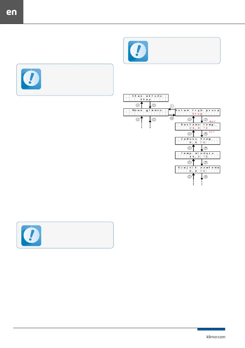
3.2 Changing set temperature
On the controller or programming device in the main menu,
“Temperature settings” parameter.
Fig. 4 Changing set temperature
Changing operating mode:
Press OK button. “Stop” starts blinking. Switch to another
mode and conrm with OK button.
Changing the temperature setting:
Press OK button “23.9..” starts blinking. Switch to another
value and conrm with OK button.
3.3 Standby mode
In order to save energy the control system is able to oper-
ate in standby mode. Select this mode using “Operation
mode” setting in the main menu of the controller or in the
timer. Depending on the requirements it is possible to set
the standby mode only for heating, only for cooling or
both for heating and cooling (see point 4.3).
Below there is a description of system reaction when
switching from the operation into standby mode (heat
-
ing).
System I – system is stopped,
System II – system is switched on for operation, fans and
heat/cool exchanger are started, master temperature is
adjusted (in this case Tsup – air supply) up to the set tem
-
perature 22°C
No system stabilization in case of such set-
tings selection can indicate wrong selection
of heat/cool exchangers, their incorrect oper-
ation, missing required parameters of heat/
cool nodes, set according to the AHU selection
sheet.
After power cut-o, the system automatically
resets to the settings operating before the power
cut-o.