55
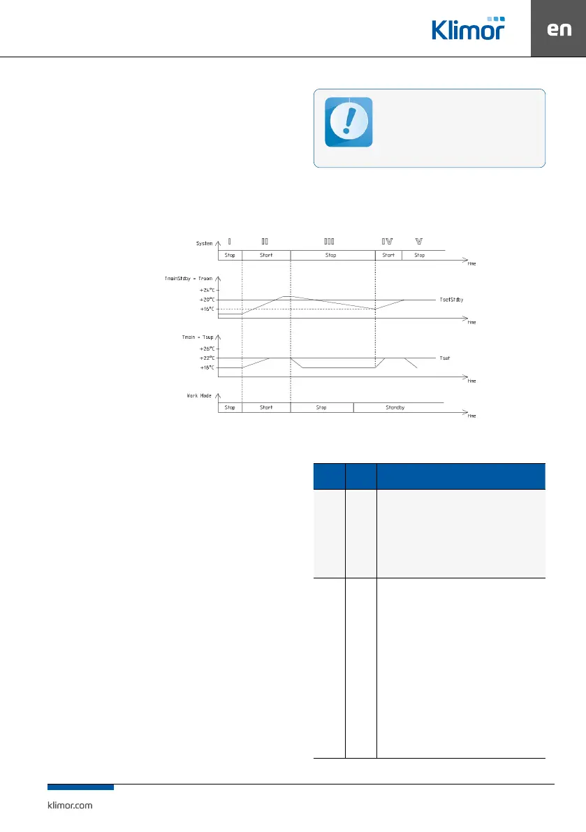
System III – the system is stopped, supplied air temperature
and room temperature is decreasing.
System IV – the system is switched on for operation because
the switch-on conditions have been reached, ie. decrease of
standby mode master temperature (in this case Troom – room
temperature) by the hysteresis value of 4°C, from the set value
TsetStdby of the standby mode = 20°C, the temperature ad
-
justment of the AHU is carried out against the master sensor
(in this case Tsup – air supply).
System V – the system is stopped because the standby mode
set temperature has been reached (Troom = TsetStdby).
For correct system operation in the standby
mode it is recommended to use an additional
room temperature sensor (connected to the
PT5 input) located in a representative room.
You can also use the HMI panel for this purpose.
Readings of air supply and exhaust tempera-
ture sensors in this mode can be unreliable.
Fig. 5 Controller operations in the standby mode
3.4 Alarms
Alarms are indicated by the display blinking and by red
LED on the controller or programming device as well
as by switching on a rely output of the Re8 controller.
Alarm description can be found in the “Alarm menu”. Hold
“C” key for about 3 seconds to access the Alarm menu. The
last position in the alarm menu is “Alarms history” menu,
where you can see the alarm history (an alarm name, it data
and time are recorded).
If the blocking alarm occurs, it is necessary to reset
the alarm in order to restart operation of the control
system. In order to reset an alarm, access the “Alarm
menu” and hold “OK” key at the selected alarm.
If an alarm source is still present, then the alarm will be
preserved and the “*” symbol appears at its description,
which means that the alarm has been conrmed. If an alarm
source is no longer present or disappears once conrmed,
the alarm will be reset. This alarm info is stored in the
“Alarms history” menu.
Table No. 10 Alarms list
Alarms
Alarm
type
System response, action / Alarms list
A_AF Fading
Cooperation with re alarm system
Normal condition – no re, 24VAC signal at digital input
Alarm condition – re, no 24VAC signal at digital input
Response to the alarm condition: system STOP till the re is
eliminated, once the re is eliminated the system automati-
cally reverts operation to the state before the alarm occurred
Digital input Din1
A_ThHWair
A_3xThWair
Fading
Blocking
Anti-frost heater protection with the anti-frost ther-
mostat
Normal condition – temperature downstream the heater is hi-
gher than temperature set on the thermostat, there is 24VAC
signal at digital input
Alarm condition – temperature downstream the heater is
lower than temperature set on the thermostat, there is no
24VAC signal at digital input
Response to the alarm condition: system STOP, heater 100%,
till the thermostat is heated up, once the thermostat is heated
up, conrm the alarm in the alarm menu, once conrmed and
if there is no low temperature present, the system resumes
the operation after triple occurrence of A_ThHWair within an
hour, the system stops working and the A_3xThHWair alarm
requiring conrmation is displayed.
Digital input Din2