56
AUTOMATION AND CONTROLLER FOR UNITS EVO-T; EVO-T COMPACT
OPERATION AND MAINTENANCE MANUAL
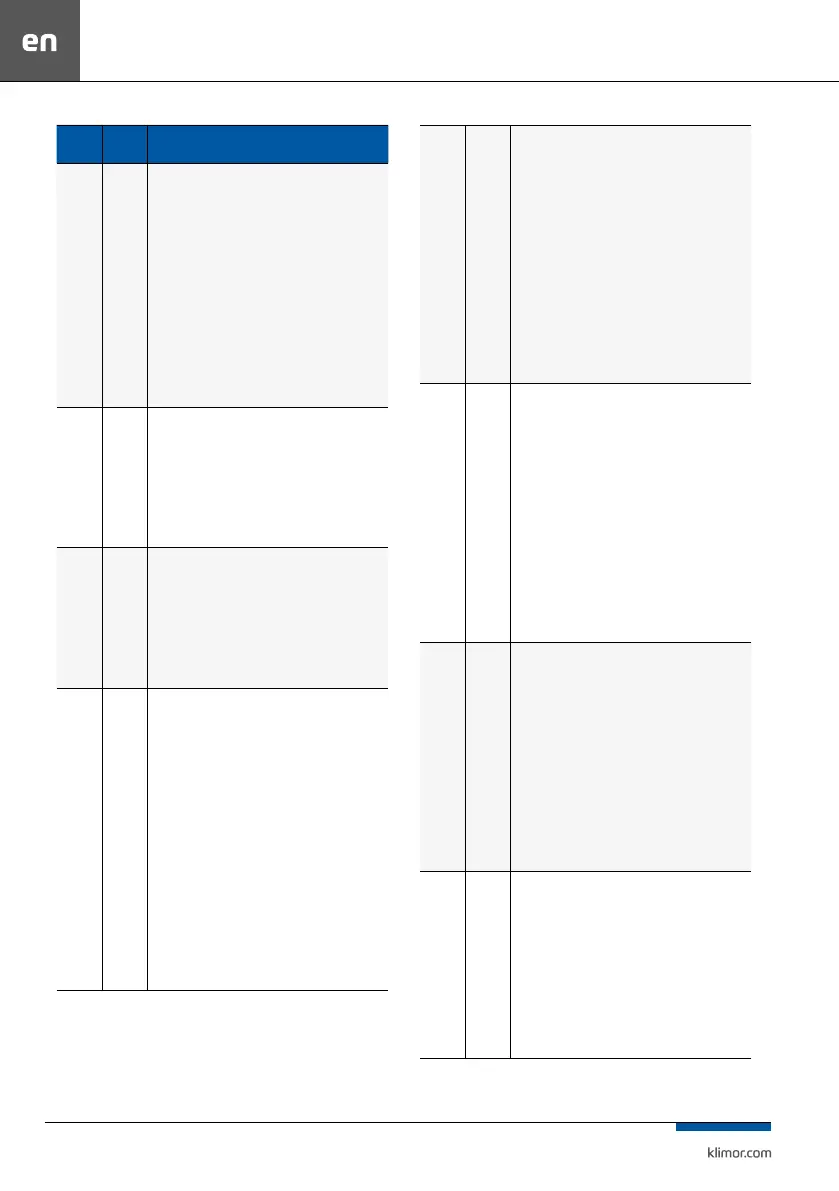
Alarms
Alarm
type
System response, action / Alarms list
A_ThHE, A_3xThHE
Fading
Blocking
Overheat protection of the electrical heater, a signal
from alarm relay of the HE module installed in the po-
wer supply control cabinet which controls the electrical
heater is feed to this input:
Normal condition – heater temperature is low, 24VAC signal on
the digital input
Alarm condition – heater temperature is too high, there is no
24VAC signal on the digital input
Response to the alarm condition: the system operates without
the heater until overheating is eliminated, once overheating is
eliminated the alarm disappears and the system operates with
the heater, if the A_ThHE alarm is triggered 3 times within
1 hour, the system is stopped and the A_3×ThHE alarm is
displays, which has to be conrmed.
Digital input Din2
A_DX Fading
Cooperation with the chiller alarm contact:
Normal condition - no chiller alarm, no 24VAC signal on the
digital input
Alarm condition - there is chiller alarm, there is a 24VAC signal
on the digital input
Response to the alarm state: information signal.
It is possible to change the NO setting to NC .
Digital input Din3
A_FX Fading
Cooperation with the reversing unit alarm contact:
Normal condition - no reversing unit alarm, no 24VAC signal on
the digital input
Alarm condition - there is reversing unit alarm, there is a 24VAC
signal on the digital input
Response to the alarm state: information signal.
It is possible to change the NO setting to NC.
Digital input Din3
A_Col-
dRec
Fading
Frosting test of the recovery outlet part with a pressure
switch:
Normal condition - there is no frosting, the pressure dierence
before and behind the recovery is below the preset value on
the pressure switch, there is no 24VAC signal on the digital
input.
Alarm condition - there is frosting, the pressure dierence
before and behind the recovery is above the preset pressure,
there is 24VAC signal on the digital input
Reaction to the alarm state: the system is in operation, the
recovery control is reduced, after the alarm has disappeared,
the system is in operation with the recovery, if the temperature
control process requires it, if the alarm does not go away for a
longer period of time the recovery system should be checked
and brought to the state from before the alarm
Digital input Din4
It is possible to use the temperature sensor for the frosting test,
see Settings/Service Menu/Recovery Sensor
Sensor input PT4
A_Sup
Filter
Fading
The air supply lter contamination level inspection
using the pressure gauge:
Normal condition – permissible contamination level, pressure
dierence downstream and upstream the lter is lower than
the one set on the pressure gauge, no 24VAC signal at digital
input
Alarm condition – unacceptable contamination level, pressure
dierence downstream and upstream the lter is higher than
the one set on the pressure gauge, 24VAC signal at digital input
Response to the alarm condition: the system operates, the con-
taminated lter alarm is displayed, if such alarm occurs, install
the new lter immediately, AHU operation with contaminated
lter can reduce the AHU eciency and can lead to the lter
damage which in turn can cause contamination and damage
of heat/cool exchangers (that would be a customer’s fault).
Digital input Din5
A_Exh
Filter
Fading
The air exhaust lter contamination level inspection
using the pressure gauge:
Normal condition – permissible contamination level, pressure
dierence downstream and upstream the lter is lower than
the one set on the pressure gauge, no 24VAC signal at digital
input
Alarm condition – unacceptable contamination level, pressure
dierence downstream and upstream the lter is higher than
the one set on the pressure gauge, 24VAC signal at digital input
Response to the alarm condition: the system operates, the con-
taminated lter alarm is displayed, if such alarm occurs, install
the new lter immediately, AHU operation with contaminated
lter can reduce the AHU eciency and can lead to the lter
damage which in turn can cause contamination and damage
of heat/cool exchangers (that would be a customer’s fault).
Digital input Din6
A_Sup-
Pres
Blocking
Air supply fan operation inspection using the pressure
gauge:
Normal condition – fan compression is examined 30 seconds
after starting the system, pressure dierence downstream and
upstream the fan should be higher than one set on the pressu-
re gauge, 24VAC signal at digital input
Alarm condition – no fan compression 30 seconds after starting
the system, pressure dierence downstream and upstream the
fan is lower than one set on the pressure gauge, no 24VAC
signal at digital input
Response to the alarm condition: the system is stopped, check
the fan and nd out the problem with compression, once the
problem is eliminated conrm the alarm and start the system
Digital input Din7
A_Sup-
FC
Blocking
Air supply fan operation inspection using the inverter
alarm contact or EC motor controller:
Normal condition – no alarm immediately after starting the
system, alarm contact is shorted, 24VAC signal at digital input
Alarm condition – alarm immediately after starting the sys-
tem, alarm contact is open, no 24VAC signal at digital input
Response to the alarm condition: the system is stopped, check
the inverter and its connection to the controller and the fan,
nd out the problem source, once the problem is eliminated
conrm the alarm and start the system.
Digital input Din9
 Loading...