MDC-1840BB/1841BB/1860BB/1810BB/1820BB Series Chapter 8
Operation Manual Trouble Shooting And On Board Servicing
93142122-07 8-15
N
Modulator PCB is faulty
Y
N
Check for cable connection
between antenna and dis
The magnetron is faulty
Y
Y
N
Modulator PCB is faulty
Y
N
Modulator PCB is faulty
Y
N
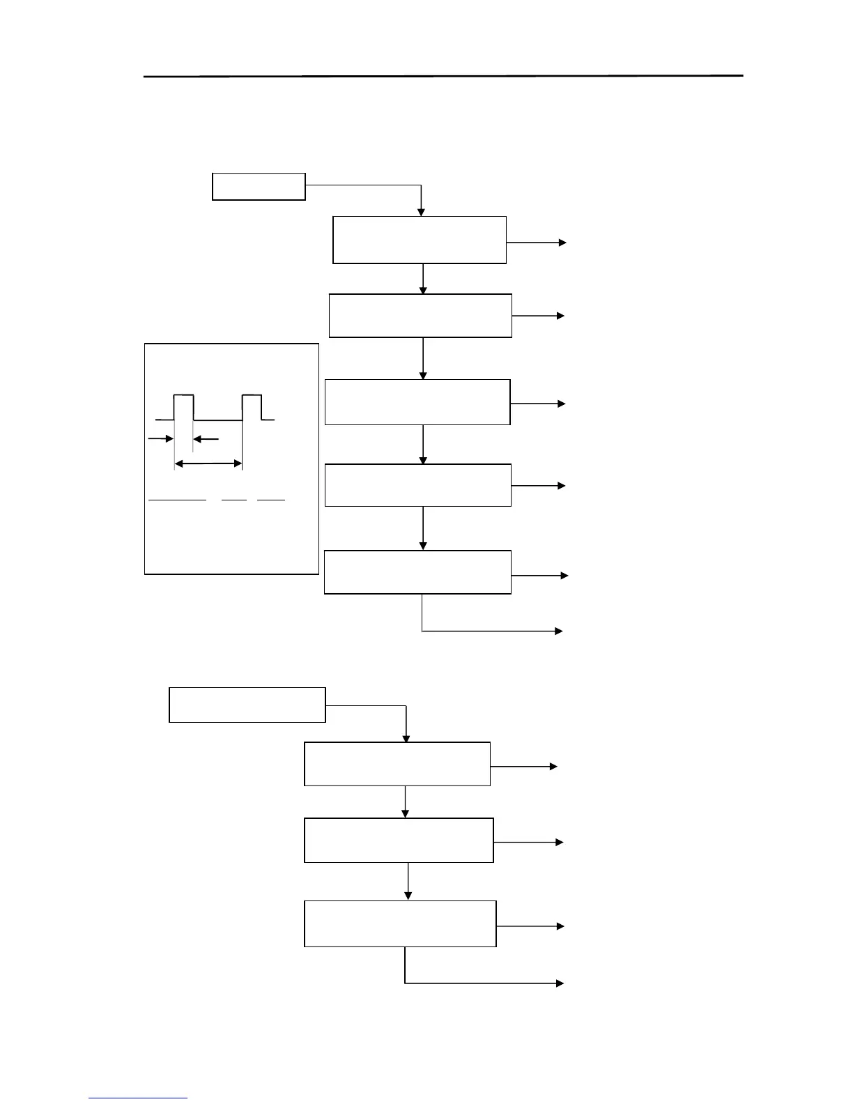
Is the Mod-HT fuse F3
normal (not blown)?
Is +250 V on J2-1
(Modulator PCB) normal?
Is the trigger signal on TP2
(Modulator PCB) normal?
Is any buzz heard from the
Pulse Transformer?
Is 6.3 V applied to the
magnetron heater?
Internal wiring in the Antenna
unit or Power Supply in the
Display unit is faulty.
Y
N
IF PCB is faulty
LNFE module is faulty
Y
Y
N
IF PCB or LNFE module is
faulty
N
Manual tuning is faulty
Is +24V supply on J1-1 (IF
Amplifier) normal?
Internal wiring in the
Antenna unit or Power
Supply in the Display unit is
faulty
Does the voltage on J2-3 (IF
PCB) vary from 6 V to 9 V?
Is +5 V supply on J2-2 (IF
PCB) normal?
Waveform on TP2
A
B
5 V
0 V
Pulse length A(ns) B(ms)
SP 100 0.5
M1 200 0.67 or 0.77
M2 550 1 or 1.25
LP 1050 2 or 2.5
No transmit
 Loading...