Chapter 4 MDC-1840BB/1841BB/1860BB/1810BB/1820BB Series
Installation Operation Manual
4-16 0093142122-11
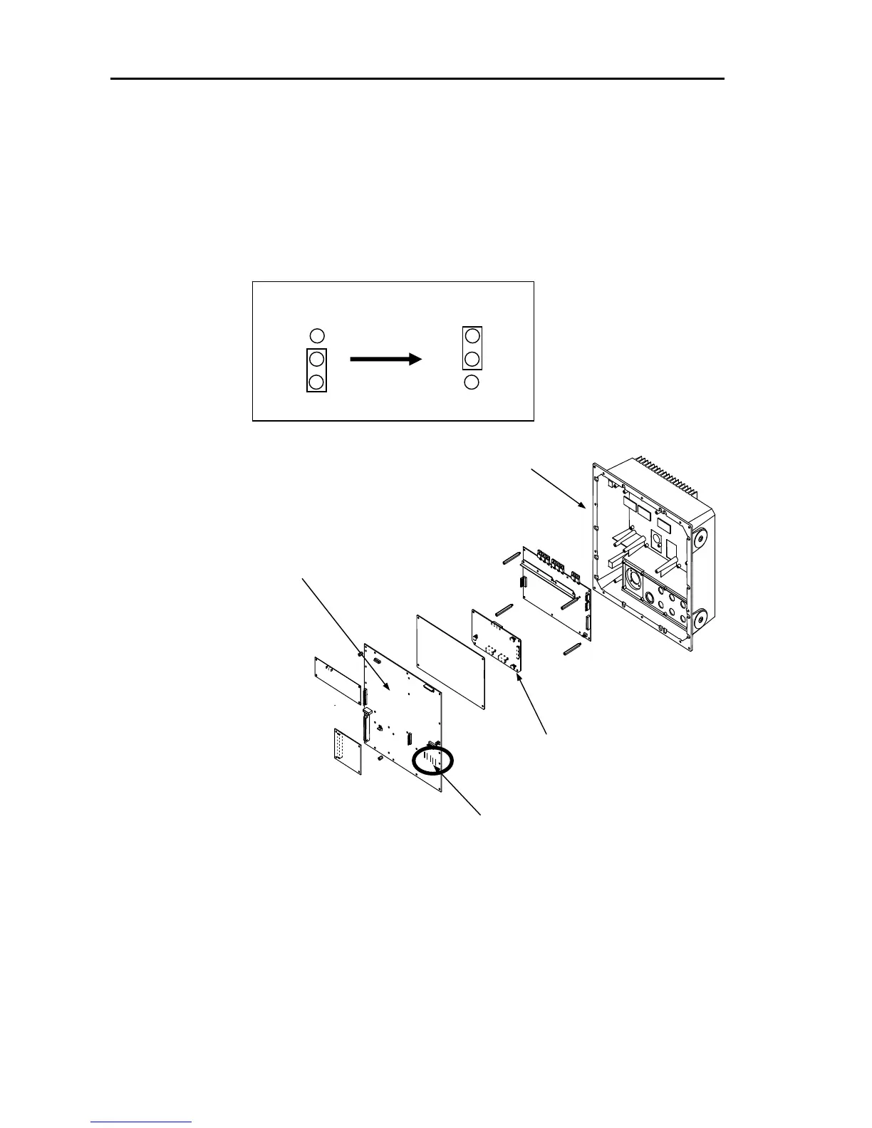
4.6.7 Link setting for the gyrocompass
When the Gyro signal voltage is lower than 50V, change the link positions for J721 to
J7125 from “2-3” to “1-2” on the Main Logic PCB (E47-700*) as shown below.
4.6.8 Ferrite core assembling for Power cable
Loop the power cable around the ferrite core three turns at position of 40 cm from the
connector as shown in figure 4.17.
1
2
3
1
2
3
Change setting from “2-3” to “1-2”,
applicable for J721 to J725
Main Logic PCB (E47-700*)
Main cabinet chassis
KSA-08A PCB module
(E47-510*)
Link pins for J721 to J725 for the
gyrocompass voltage setting
Figure 4.16 Locations of the gyrocompass links on the Main Logic PCB