TP-6745 7/10 17Section 1 Scheduled Maintenance
Service Reconnect Procedure (when Normal
source is NOT available)
Manually operate the ATS to the Normal position before
returning the generator set to service, as described in
the procedure below.
1. Verify that the generator set master switch is in the
OFF position.
2. Open the ATS enclosure and manually transfer the
ATS to utility. (Open the emergency breaker and
close the utility breaker. See the ATS Operation
Manual for instructions, if necessary.) Then close
and secure the enclosure door.
3. Return the generator set to service:
a. Reconnect the battery cables, negative lead
last.
b. Reconnect power to the battery charger.
c. Move the generator set master switch to the
AUTO position.
4. When the generator source is available, the ATS
transfers to emergency.
5. Remove the padlock from the service disconnect
control switch and move the service disconnect
switch to the AUTO position.
6. Reset faults on the controller, if necessary.
7. Verify that the ATS controller display shows
emergency source available and ATS in
emergency position. The service disconnect light
on the door should be off.
1.7 Control Circuit Isolation
Switch
The two-position control circuit isolation switch removes
utility power from the ATS controller assembly.
Note: Perform the service disconnect procedure
explained in Section 1.6.1 before operating the
control circuit isolation switch.
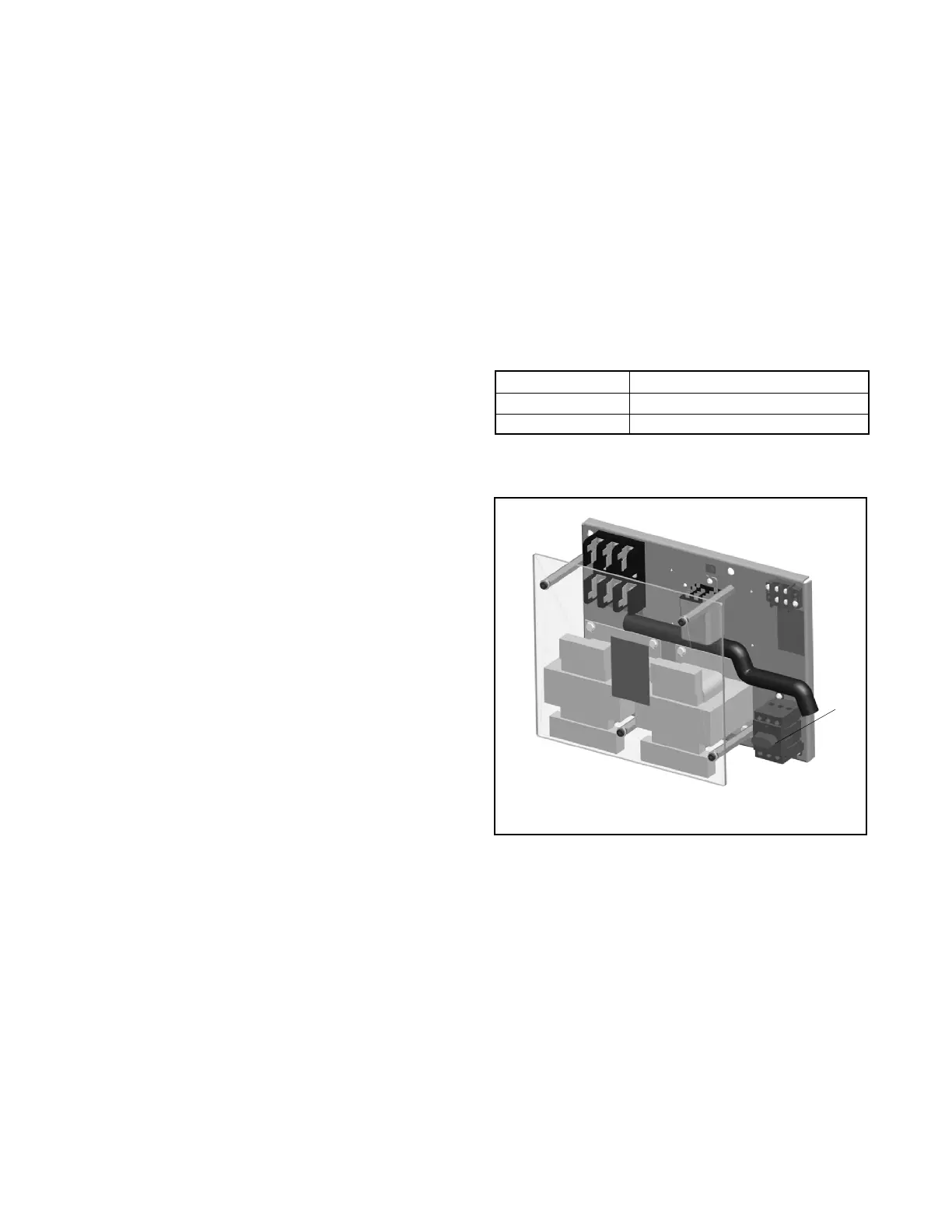
See Figure 1-3 for switch positions. The control circuit
isolation switch is mounted on the transformer
assembly. See Figure 1-4. The location of the
transformer assembly varies with ATS model and
enclosure size. See Figure 1-5 and Figure 1-6 for
typical locations.
Switch Position Utility Power to Controller
ON Connected
OFF Disconnected
Figure 1-3 Control Circuit Isolation Switch
Positions
GM69797
1
1. Control circuit isolation switch
Figure 1-4 Control Circuit Isolation Switch
Location on Transformer Assembly

 Loading...

