TP-6745 7/1024 Section 2 Troubleshooting
Voltage, Frequency, and Phase Rotation Check
Procedure
1. Ensure that all downstream loads are switched off.
2. If the source being measured is a generator set,
start the generator set by moving the master switch
to RUN.
3. Use a voltmeter to check the source
phase-to-phase and phase-to-neutral (if
applicable) terminal voltages and frequency.
a. If Source N is the utility and the measured input
does not match the voltage and frequency
shown on the transfer switch nameplate,
STOP! Do not proceed further in installation
because the transfer switch is not designed for
the application. See Section 2.5 for instructions
to correct the input voltage transformer
connections and contact your distributor/dealer
to order the correct nameplate.
b. If the source is a generator set and the
generator set output voltage and frequency do
not match the nominal system voltage and
frequency shown on the transfer switch
nameplate, follow the manufacturer’s
instructions to adjust the generator set. The
automatic transfer switch will only function with
the rated system voltage and frequency
specified on the nameplate.
4. Use a phase rotation meter to check the phase
rotation at the source terminals. Rewire the
transfer switch source terminals to obtain the
correct phase sequence if necessary.
Note: The default setting for the phase rotation on
the controller is ABC. If the application uses
a phase rotation of BAC, use the Source
Setup screen to change the phase rotation
setting on the controller.
5. If the source is a generator set, stop the generator
set by moving the master switch to the
OFF/RESET position.
6. Repeat steps 2 through 5 for Source E.
7. Close and lock the transfer switch enclosure door.
8. Perform the Lamp Test and then proceed to the
Automatic Operation Test.
2.5 System Settings
If the ATS does not recognize the source, check that the
source voltage and frequency settings on the controller
match the actual source parameters.
Compare the controller settings to the ratings on the
ATS nameplate and to the measured source
parameters using the following instructions.
2.5.1 Controller Source Settings
Check the controller’s source voltage, frequency, and
phase settings. See the transfer switch operation and
installation manual for instructions.
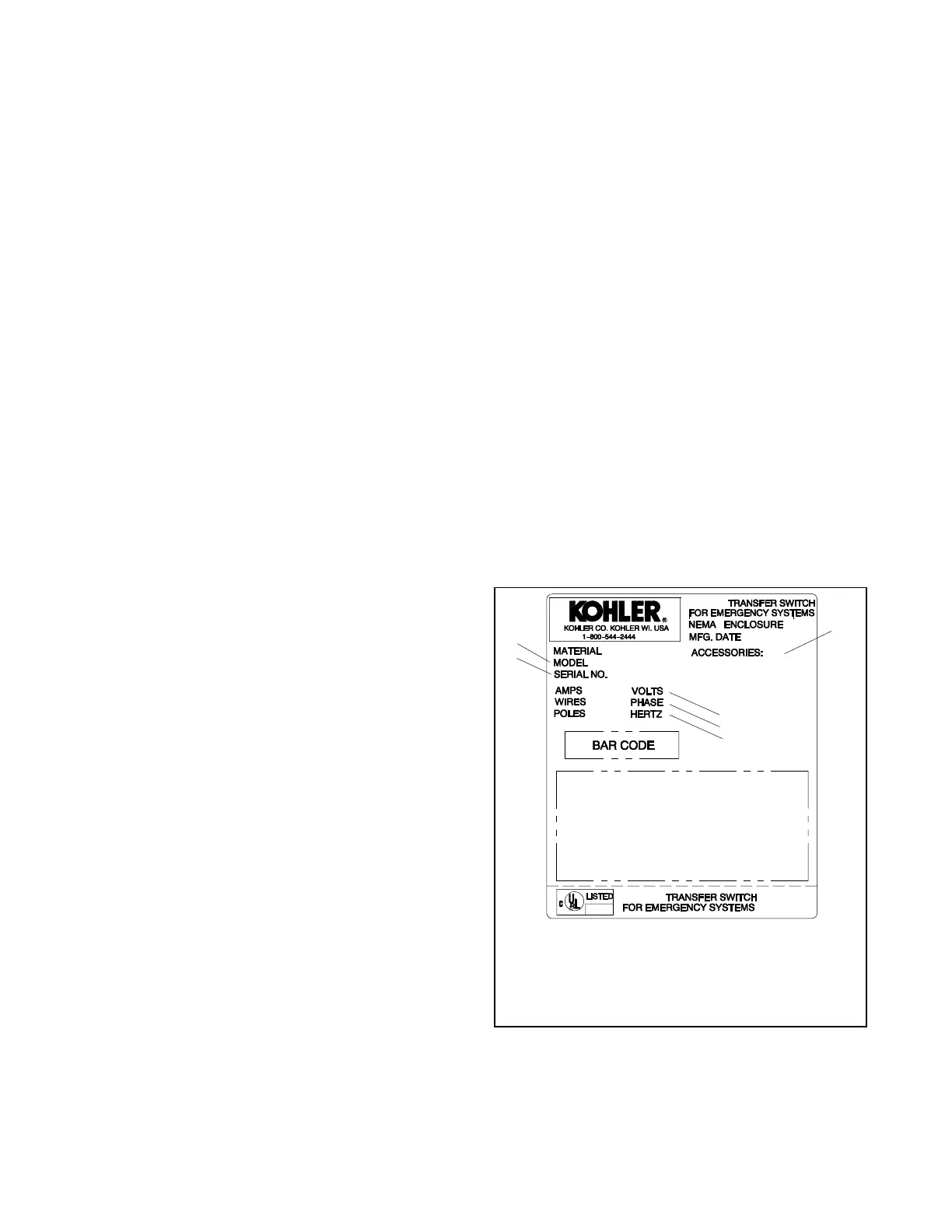
Check the controller settings and compare them to the
voltage rating, frequency rating, and number of phases
shown on the ATS nameplate. The nameplate is
attached to the cover of the controller assembly, which is
mounted on the inside of the transfer switch door. See
Figure 2-5 for an illustration of the nameplate.
Note: The system voltage and frequency shown on the
ATS nameplate must match the Source N and
Source E voltage and frequency settings. Do not
enter settings that do not match the nameplate
ratings of the ATS.
GM21291
1
2
3
1. Model designation
2. Serial number
3. Factory-installed accessory numbers
4. Voltage rating
5. Frequency rating
6. Number of phases (single or three)
4
5
6
Figure 2-5 Typical Transfer Switch Nameplate

 Loading...

