TP-6745 7/10 49Section 3 Controller Test and Replacement
GM46733
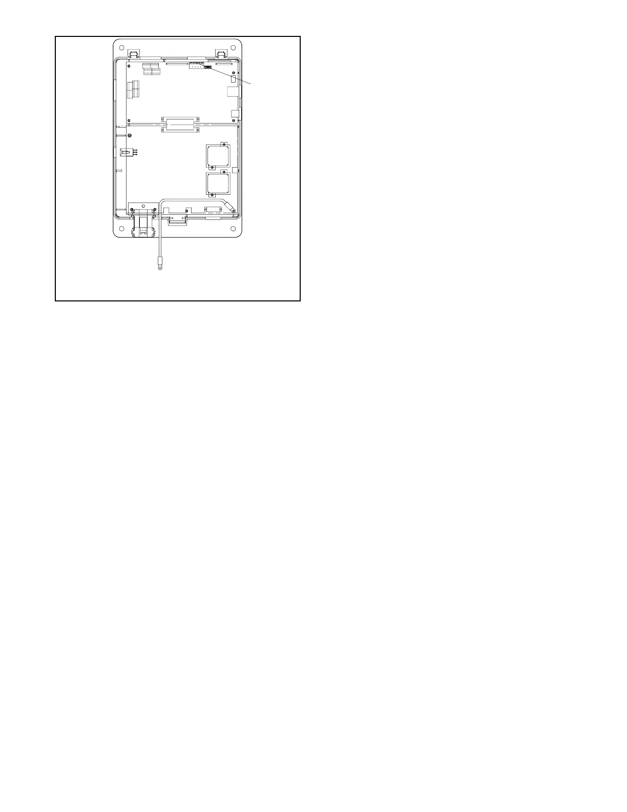
1. Connect service kit power cable to controller
connector P16 (I/O module connection)
1
Figure 3-6 Service Kit GM52407 Connection
(controller cover removed for illustration
only)
3.4 Sequence of Operation
3.4.1 Controller Powerup Reset
Sequence of Operation
Following is an explanation of the sequence of operation
for the MPACt 1500 ATS Controller when power is
initially applied to the controller or a controller reset
occurs.
1. Controller self test is executed.
2. System parameters are downloaded from
non-volatile memory.
3. Power switching device position and source
availability are determined.
4. If neither source is acceptable, the power switching
device does not change position.
5. If both sources are available, the controller
immediately transfers the power switching device
to the preferred source.
6. If only one source is available, the controller
immediately transfers the power switching device
to that source, executing only the off-position and
load control time delays.
If the available source is the preferred source, and
the power switching device was in the standby
position, the power switching device transfers to
preferred, the engine cooldown time delay runs,
and then the engine start contacts open.
If the available source is the preferred source and
the power switching device was already in the
preferred position, the engine start contacts open
immediately, bypassing the engine cooldown time
delay.