TP-6745 7/10 45Section 3 Controller Test and Replacement
Section 3 Controller Test and Replacement
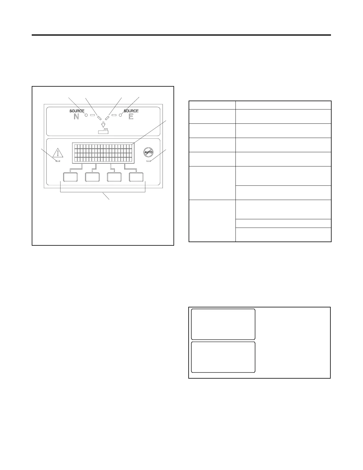
3.1 User Interface Panel
The user interface panel is located on the transfer switch
door. Figure 3-1 shows the user interface pushbuttons
and LED indicators.
1 2 3 4
GM46892
1. Source N Available LED
2. Source N Position LED
3. Source E Position LED
4. Source E Available LED
5. Display
6. Not in Auto LED
7. Pushbuttons (4)
8. System Alert LED
6
7
8
5
Figure 3-1 User Interface Panel
3.1.1 Display
The four-line display indicates transfer switch status and
setup, including the following:
D System status
D Faults and warnings
D Active time delays
D Source voltages
D Source frequency (Hz)
D Current (amps)
D Source setup information
D Time and date
D Time and date of next scheduled exercise
The display also identifies the pushbutton functions,
which can change from screen-to-screen.
3.1.2 LED Indicators
LEDs on the user interface indicate power switching
device position, source availability, faults, and other
conditions. Figure 3-2 describes the functions of the
LED indicators. See Section 2.8 for more information
about warnings and faults.
LED Indicator Condition
Source N
Available, Green
Source N is available.
Source E
Available, Red
Source E is available.
Position A, Green power switching device is in Normal
position.
Position B, Red power switching device is in
Emergency position.
System Alert,
Red
Fault. Identify and correct the cause
of the fault condition, then reset faults
at the controller. See Section 2.8.
Input active: Low Battery Voltage or
Remote Common Alarm.
Not in Auto, Red ATS is not set for automatic operation
or a load shed (forced transfer to
OFF) sequence is active.
Flashes for manual transfer waiting.
Input active: Inhibit Transfer or
Forced Transfer to OFF.
Figure 3-2 User Interface LED Indicators
3.1.3 Lamp Test
To test the LEDs on the controller’s user interface, go to
the Main screen. Press the down arrow button once,
then press the Lamp Test button and verify that all
6 LEDs on the user interface illuminate. See Figure 3-3.
System Ready
LD Exer 12/14 @ 16:00
Norm 480V Emer 480V
B View Set Test
Norm AB BC AC
##Hz ###V ###V ###V
Lamp
BYTest Main
Press the down arrow
button.
Press and hold the
Lamp Test button.
Figure 3-3 Lamp Test

 Loading...


